EP0519243B1 - Backen für eine Tourenskibindung - Google Patents
Backen für eine Tourenskibindung Download PDFInfo
- Publication number
- EP0519243B1 EP0519243B1 EP92109028A EP92109028A EP0519243B1 EP 0519243 B1 EP0519243 B1 EP 0519243B1 EP 92109028 A EP92109028 A EP 92109028A EP 92109028 A EP92109028 A EP 92109028A EP 0519243 B1 EP0519243 B1 EP 0519243B1
- Authority
- EP
- European Patent Office
- Prior art keywords
- locking
- jaw
- accordance
- locking piece
- bearer
- Prior art date
- Legal status (The legal status is an assumption and is not a legal conclusion. Google has not performed a legal analysis and makes no representation as to the accuracy of the status listed.)
- Expired - Lifetime
Links
Images


Classifications
-
- A—HUMAN NECESSITIES
- A63—SPORTS; GAMES; AMUSEMENTS
- A63C—SKATES; SKIS; ROLLER SKATES; DESIGN OR LAYOUT OF COURTS, RINKS OR THE LIKE
- A63C7/00—Devices preventing skis from slipping back; Ski-stoppers or ski-brakes
- A63C7/10—Hinged stoppage blades attachable to the skis in such manner that these blades can be moved out of the operative position
- A63C7/1006—Ski-stoppers
- A63C7/1013—Ski-stoppers actuated by the boot
-
- A—HUMAN NECESSITIES
- A63—SPORTS; GAMES; AMUSEMENTS
- A63C—SKATES; SKIS; ROLLER SKATES; DESIGN OR LAYOUT OF COURTS, RINKS OR THE LIKE
- A63C9/00—Ski bindings
- A63C9/08—Ski bindings yieldable or self-releasing in the event of an accident, i.e. safety bindings
- A63C9/0805—Adjustment of the toe or heel holders; Indicators therefor
-
- A—HUMAN NECESSITIES
- A63—SPORTS; GAMES; AMUSEMENTS
- A63C—SKATES; SKIS; ROLLER SKATES; DESIGN OR LAYOUT OF COURTS, RINKS OR THE LIKE
- A63C9/00—Ski bindings
- A63C9/08—Ski bindings yieldable or self-releasing in the event of an accident, i.e. safety bindings
- A63C9/0807—Ski bindings yieldable or self-releasing in the event of an accident, i.e. safety bindings for both towing and downhill skiing
-
- A—HUMAN NECESSITIES
- A63—SPORTS; GAMES; AMUSEMENTS
- A63C—SKATES; SKIS; ROLLER SKATES; DESIGN OR LAYOUT OF COURTS, RINKS OR THE LIKE
- A63C9/00—Ski bindings
- A63C9/08—Ski bindings yieldable or self-releasing in the event of an accident, i.e. safety bindings
- A63C9/084—Ski bindings yieldable or self-releasing in the event of an accident, i.e. safety bindings with heel hold-downs, e.g. swingable
- A63C9/0845—Ski bindings yieldable or self-releasing in the event of an accident, i.e. safety bindings with heel hold-downs, e.g. swingable the body or base or a jaw pivoting about a vertical axis, i.e. side release
-
- A—HUMAN NECESSITIES
- A63—SPORTS; GAMES; AMUSEMENTS
- A63C—SKATES; SKIS; ROLLER SKATES; DESIGN OR LAYOUT OF COURTS, RINKS OR THE LIKE
- A63C9/00—Ski bindings
- A63C9/08—Ski bindings yieldable or self-releasing in the event of an accident, i.e. safety bindings
- A63C9/084—Ski bindings yieldable or self-releasing in the event of an accident, i.e. safety bindings with heel hold-downs, e.g. swingable
- A63C9/0846—Details of the release or step-in mechanism
-
- A—HUMAN NECESSITIES
- A63—SPORTS; GAMES; AMUSEMENTS
- A63C—SKATES; SKIS; ROLLER SKATES; DESIGN OR LAYOUT OF COURTS, RINKS OR THE LIKE
- A63C9/00—Ski bindings
- A63C9/08—Ski bindings yieldable or self-releasing in the event of an accident, i.e. safety bindings
- A63C9/086—Ski bindings yieldable or self-releasing in the event of an accident, i.e. safety bindings using parts which are fixed on the shoe of the user and are releasable from the ski binding
-
- A—HUMAN NECESSITIES
- A63—SPORTS; GAMES; AMUSEMENTS
- A63C—SKATES; SKIS; ROLLER SKATES; DESIGN OR LAYOUT OF COURTS, RINKS OR THE LIKE
- A63C9/00—Ski bindings
- A63C9/08—Ski bindings yieldable or self-releasing in the event of an accident, i.e. safety bindings
- A63C9/084—Ski bindings yieldable or self-releasing in the event of an accident, i.e. safety bindings with heel hold-downs, e.g. swingable
- A63C9/0844—Ski bindings yieldable or self-releasing in the event of an accident, i.e. safety bindings with heel hold-downs, e.g. swingable the body pivoting about a transverse axis
Definitions
- the invention relates to a jaw for a touring ski binding with the features of the preamble of claim 1.
- Jaws of a similar type have become known for safety ski bindings (DE-OS 20 34 124, DE-OS 23 04 929, DE-OS 31 41 021, DE-AS 15 78 761), the catch formed from the compression spring, pressure member and locking recess being the task has to loosen the connection between the boot and the binding if a force acting on the skier acts on the boot.
- the jaws can be pivoted around the catch carrier.
- the contact pressure of the compression spring and thus the release force is adjustable.
- Such notches in these jaws can be triggered both by transverse forces and by forces acting upwards from the ski.
- the pressure members interacting with the locking trough are spherical or as truncated cones. Depending on the geometry of the structural parts interacting here, the ratio of the horizontal and the vertical release force is essentially constant regardless of the respective spring preload, which can be set.
- this jaw can assume at least two positions, the pivoting part of the jaw being pivotable by at least 180 ° about a vertical axis. On this angular path of 180 °, three operating positions are provided for the swivel part. For the descent, the shoe is held directly in the one position of the cheek on the ski. The two other positions serve to support the shoe when climbing, the two positions differing in the different heights of the supports for the shoe.
- a spring is provided which interacts with a catch and which is adjustable in terms of its preload, this jaw, however, can only be triggered by transverse forces.
- the invention is based on this prior art and it aims to design a toe for touring ski bindings in such a way that it can be triggered not only by transverse but also by vertical forces, the ratio of the triggering forces in the transverse and The vertical direction should be changeable in order to be able to optimally adjust the jaws serving as a safety element to the respective constitution of the skier. According to the invention, this complex problem is solved by those features which are the content and subject of the characterizing part of patent claim 1.
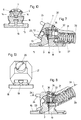
- the latch support 1 for the jaws is made in several parts. It has a base body 2, which is connected to a base plate 3 (FIG. 5) in a suitable form or is integrally formed with it.
- This base body 2 is spherical in the embodiment shown, that is. that is, its outer envelope lies on a spherical surface, but this spherical shape is not mandatory for it.
- This base body 2 is cut out in its upper rear part and in this cutout there are two identically designed, mirror-symmetrically arranged wedges 4, the wedge surfaces 5 of which face one another and which converge downwards.
- a spreading wedge 6 is provided between these two wedges 4 and adjoining their wedge surfaces 5 and is penetrated in the vertical direction by an adjusting screw 7.
- the wedges 4 are guided on the expansion wedge 6 by a dovetail guide 8, the expansion wedge 6 by a dovetail guide 9 on the base body 2.
- the two wedges 4 form with their rear surface a locking trough 10, the surfaces forming this locking trough 10 being cylindrically curved.
- the axes or generatrices of these cylindrically curved surfaces lie horizontally and transversely to the longitudinal axis of the ski.
- two latching troughs 12 and 13 are also provided, these are also as partial cylinder surfaces formed and lie one above the other, the upper locking troughs 10 and 12 of the locking support 1 and the lower locking troughs 11 and 13 are each arranged in approximately the same horizontal planes.
- the catch carrier 1 there are recesses 14 extending laterally between the rear catch recess 10, the contact width of which can be changed, and the front catch recess 12.
- the base plate 3, which carries the catch carrier 1, is pivotably articulated on a mounting plate 15.
- the pivot axis is formed by journals 16, which lie in front of the catch support 1, the catch support 1 being supported with its rear side relative to the mounting plate 15 on elastic supports 17, for example rubber pads or small spring assemblies.
- an undercut recess 18 is provided starting from the underside of the catch carrier 1, into which a retainer 19, here of a T-shaped cross section, engages positively and with sufficient play (Fig. 10).
- the set screw 7 is screwed into a threaded bore of the catch carrier 1 and the expansion wedge 6 is held between the head and a catch disc 20 fixed to the screw. So much for the structural design and geometry of the latch bracket 1.
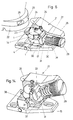
- Fig. 6 illustrates the jaw with the above-described locking block 1 in an oblique view and cut open.
- the pivoting part 21, which is adjustable or pivotable with respect to the latch support 1 both in a vertical plane and about a vertical axis, has on its side facing the ski boot 22 a tread bar 23 and retaining lugs 24 which are provided in pairs and which, when the binding is used as intended Corresponding openings 25 cooperate holding on the ski boot.
- a longitudinal bore 27 is provided for receiving a compression spring 28, which bears on the one hand against an adjusting screw 29 which can be actuated from the outside, and on the other hand on a molded part 30, which in turn rests directly on the pressure member 31.
- this pressure member 31 is designed as a circular cylinder, on the two ends of which links 32 are fastened, which can be pivoted about an axis 33 lying above the pressure member 31, this axis in turn being mounted in the pivot part 21.
- the adjusting screw 7 is accessible via this opening 34.
- the pivoting part 21 encloses the catch carrier 1, delimited by a spherical contour, in the manner of a spherical socket. So much for the structure of the heel cheek.
- Fig. 7 illustrates in longitudinal section the jaws, in its open position.
- the pivot part 21 is pivoted downward with its rear part, which encloses the compression spring 38, the jaws is open.
- the sole of the ski shoe exerts a downward force on the kick bar 23 so that the front part of the cheek tilts downward into the position shown in FIG. 8.
- the pressure member 31 passes from the lower locking trough 11 into the upper locking trough 10.
- the size of the triggering force depends on how far apart the wedges 4 are, because with such a transverse triggering the cylindrical pressure member 31, which is acted upon by the compression spring 28 in the middle to tilt one of the two outer edge edges 35 of the locking recess 10. With a predetermined force exerted by the compression spring 28, this triggering force is greater the further the two wedges 4 forming the locking trough 10 are spaced apart from one another.
- the plug 36 is removed from the opening 34, making the adjusting screw 7 accessible through this opening. By turning the adjusting screw 7, the expanding wedge 6 is raised or lowered, specifically with respect to the catch carrier 1, which means that the wedges 4 become due to the positive guidance approach each other or move apart.
- the jaw has only one compression spring 28, which can be adjusted with regard to its pretension via the adjusting screw 8, the ratio of the triggering forces in the transverse and vertical directions can be varied to a considerable extent thanks to the variability of the contact width of the locking trough 10.
- the pressure member 31 is designed as an independent component and is mounted on the housing of the swivel part 21 via link 32.
- the external forces which act on the swivel part 21 are transmitted directly to the pressure member via the link 32 and introduced to the latter.
- the molded part 30 it would be possible to design the molded part 30 with a cylindrical, front section which interacts directly with the locking recess. In this case, the external forces mentioned must be transmitted and introduced via the housing of the swivel part 21 and the molded part 30.
- Such a construction has unfavorable friction conditions.
- the pressure member 31 is designed as a cylinder with a circular cross section, other cross sections could also be used, for example oval cross sections or egg-shaped cross sections.
- the distance between the front jaws and the jaws of a ski binding changes due to the terrain-related deflection of the ski. These changes in length are small.
- the ratchet bracket 1 and with it the swivel part 21 is arranged on a swivel-mounted base plate 3, but the extent of the deflection is limited by the play with which the retainer 19 is received by the recess 18.
- the radius of curvature of the locking trough 10 and that of the pressure member 31 are different, the radius of curvature of the locking trough 10 is larger.
- the jaws or the swivel part 21 are rotated about a vertical axis by approximately 180 °, the position shown in FIG. 8 serving as the starting position.
- the pressure member 31 is tilted over one of the edges 35 of the locking recess 10 and then passes through the trough-like recesses 14 in the locking piston 1 into the front upper locking recess 12.
- the extension 26 of the pivoting part 21 serves as a footprint for the ski boot.
- the pivoting part 21 can assume two different positions in this forward-pivoted position, which differ by the contact height, whereby the angular offset of the two locking recesses 12 and 13 prevents this, that the pivoting part 21 automatically moves from its upper position to its lower position or vice versa.
- the swivel part 21 encloses the latching support 1 in the manner of a ball socket.
- a freely rotatably mounted turntable 37 is provided between the latching support 1 and the base plate 3 with diametrically arranged, mutually aligned axle journals 38.
- the pivoting part 21 is mounted here in these axle journals. This favors the stress conditions of the swivel part 21. Otherwise, the structure of this heel shoe according to FIG. 14 corresponds to the previously discussed embodiment.
- the different positions of the baking during ascent and descent can be used advantageously for a ski stop.
- the stopper When the climbing aids are in use, i.e. on the ascent, the stopper must be folded in, which is part of the baking, e.g. a kind of cam, can accomplish. If the jaw is now swiveled into the downhill position, it releases the stopper, which swings into the "working position” and can now be pressed down with the shoe for the downhill run. If the binding is released, the stopper folds out due to the missing shoe.
- Another advantage is that the skier does not have to consider whether he has the stop function "switched on" or not.
Applications Claiming Priority (2)
| Application Number | Priority Date | Filing Date | Title |
|---|---|---|---|
| AT1248/91 | 1991-06-21 | ||
| AT0124891A AT396553B (de) | 1991-06-21 | 1991-06-21 | Backen für eine tourenskibindung |
Publications (2)
| Publication Number | Publication Date |
|---|---|
| EP0519243A1 EP0519243A1 (de) | 1992-12-23 |
| EP0519243B1 true EP0519243B1 (de) | 1995-04-26 |
Family
ID=3509804
Family Applications (1)
| Application Number | Title | Priority Date | Filing Date |
|---|---|---|---|
| EP92109028A Expired - Lifetime EP0519243B1 (de) | 1991-06-21 | 1992-05-29 | Backen für eine Tourenskibindung |
Country Status (3)
| Country | Link |
|---|---|
| EP (1) | EP0519243B1 (zh-CN) |
| AT (2) | AT396553B (zh-CN) |
| DE (1) | DE59202008D1 (zh-CN) |
Cited By (1)
| Publication number | Priority date | Publication date | Assignee | Title |
|---|---|---|---|---|
| US10463946B2 (en) | 2017-06-07 | 2019-11-05 | G3 Genuine Guide Gear Inc. | Touring binding heel unit |
Families Citing this family (14)
| Publication number | Priority date | Publication date | Assignee | Title |
|---|---|---|---|---|
| EP2259850B2 (en) | 2008-02-29 | 2023-03-15 | G3 Genuine Guide Gear Inc. | Heel unit for alpine touring binding |
| DE202009019128U1 (de) | 2008-04-03 | 2016-11-29 | G3 Genuine Guide Gear Inc. | Zeheneinheit für Tourenskibindung |
| EP2181736B1 (de) * | 2008-10-31 | 2012-08-08 | Rottefella AS | Fersenbacken mit zwei Auslösenrichtungen |
| ITTO20090430A1 (it) * | 2009-06-05 | 2010-12-06 | Stefano Maruelli | Dispositivo stabilizzatore |
| DE102010028764A1 (de) * | 2010-05-07 | 2011-11-10 | Salewa Sport Ag | Ferseneinheit für eine Bindung, insbesondere Tourenskibindung |
| IT1401139B1 (it) * | 2010-07-23 | 2013-07-12 | Ski Trab S R L | Scarpone da sci alpinistico con tacco dotato di mezzi di aggancio per talloniere di attacchi da sci alpinistico |
| IT1403536B1 (it) * | 2011-01-28 | 2013-10-31 | Atk Race Srl | Talloniera per un attacco da sci-alpinismo |
| ITTV20110063A1 (it) * | 2011-05-13 | 2012-11-14 | Tasci S R L | Attacco per l'ancoraggio di uno scarpone da scialpinismo su uno sci da discesa o similare |
| ITTV20110062A1 (it) | 2011-05-13 | 2012-11-14 | Tasci S R L | Attacco per l'ancoraggio di uno scarpone da scialpinismo su uno sci da discesa o similare |
| ITTV20110064A1 (it) | 2011-05-13 | 2012-11-14 | Tasci S R L | Attacco per l'ancoraggio di uno scarpone da scialpinismo su uno sci da discesa o similare |
| DE102011082612A1 (de) | 2011-09-13 | 2013-03-14 | SALEWA Sportgeräte GmbH | Ferseneinheit für eine Tourenbindung |
| US9242167B2 (en) | 2013-07-09 | 2016-01-26 | G3 Genuine Guide Gear Inc. | Ski binding heel unit |
| DE102016014950A1 (de) | 2015-12-18 | 2017-06-22 | Mark Richard Mosher | Verbesserte Fersenfreiheit für Tourenskibindung |
| US10315099B2 (en) | 2017-10-31 | 2019-06-11 | G3 Genuine Guide Gear Inc. | Lightweight touring binding heel unit |
Family Cites Families (6)
| Publication number | Priority date | Publication date | Assignee | Title |
|---|---|---|---|---|
| DE1578761C3 (de) * | 1967-12-19 | 1974-08-15 | Josef Ess, Allgaeuer Skibeschlaegefabrik, 8972 Sonthofen | Sicherheitsskibindungselement |
| CH512925A (fr) * | 1969-07-14 | 1971-09-30 | Salomon Georges P J | Dispositif de fixation d'une chaussure sur un ski |
| DE2304929A1 (de) * | 1973-02-01 | 1974-08-08 | Ess Skibeschlag | Sicherheitsskibindung |
| DE3141021A1 (de) * | 1981-10-15 | 1983-04-28 | Etablissements François Salomon et Fils, 74011 Annecy, Haute-Savoie | Sicherheits-schibindung |
| US4550929A (en) * | 1983-08-10 | 1985-11-05 | Buel G Theodore | Ski boot heel binding |
| AT381458B (de) * | 1985-03-25 | 1986-10-27 | Barthel Fritz | Tourenskibindung |
-
1991
- 1991-06-21 AT AT0124891A patent/AT396553B/de not_active IP Right Cessation
-
1992
- 1992-05-29 DE DE59202008T patent/DE59202008D1/de not_active Expired - Fee Related
- 1992-05-29 AT AT92109028T patent/ATE121639T1/de not_active IP Right Cessation
- 1992-05-29 EP EP92109028A patent/EP0519243B1/de not_active Expired - Lifetime
Cited By (1)
| Publication number | Priority date | Publication date | Assignee | Title |
|---|---|---|---|---|
| US10463946B2 (en) | 2017-06-07 | 2019-11-05 | G3 Genuine Guide Gear Inc. | Touring binding heel unit |
Also Published As
| Publication number | Publication date |
|---|---|
| DE59202008D1 (de) | 1995-06-01 |
| EP0519243A1 (de) | 1992-12-23 |
| AT396553B (de) | 1993-10-25 |
| ATE121639T1 (de) | 1995-05-15 |
| ATA124891A (de) | 1993-02-15 |
Similar Documents
| Publication | Publication Date | Title |
|---|---|---|
| EP0519243B1 (de) | Backen für eine Tourenskibindung | |
| DE2502956C2 (de) | Sohlenniederhalter für eine Ski-Sicherheitsbindung | |
| DE2402974A1 (de) | Kombination aus skistiefel und skibindung | |
| DE69916098T2 (de) | Sicherheitsskibindung | |
| AT390889B (de) | Vorderbacken | |
| DE3515847A1 (de) | Seitenbacken-verriegelung | |
| DE2221105B2 (de) | Sicherheits-Skibindung | |
| EP0302309B1 (de) | Vorderbacken für Sicherheits-Skibindungen | |
| DE3031611A1 (de) | Backen einer skibindung | |
| DE2364298C2 (de) | Auslöse-Haltevorrichtung für Sicherheitsskibindungen | |
| DE3925164C2 (zh-CN) | ||
| EP0389757B1 (de) | Vorderbacken | |
| EP0394380B1 (de) | Sicherheitsskibindung | |
| DE2802775C2 (de) | Sicherheitsskibindung mit einem um eine Querachse schwenkbaren Gehäuse | |
| DE4435960C2 (de) | Snowboardbindung | |
| DE1930997C3 (de) | Vorderbacken für Sicherheits-Skibindungen | |
| DE2528017C3 (de) | Verriegelungsorgan für eine Skibindung | |
| EP0344249A1 (de) | Backen, insbesondere einen vorderbacken | |
| DE2600858B2 (de) | Skisicherheitsbindung mit einer mit dem Schuh lösbar verbundenen Trittplatte | |
| DE3411897C2 (zh-CN) | ||
| EP0340623B1 (de) | Vorderbacken | |
| DE4022945A1 (de) | Sicherheitsskibindung mit verschwenkbarer sohlenplatte | |
| EP0111886A2 (de) | Auslöseskibindung | |
| AT375265B (de) | Sicherheitsskibindung | |
| EP0114663B1 (de) | Auslöseskibindung |
Legal Events
| Date | Code | Title | Description |
|---|---|---|---|
| PUAI | Public reference made under article 153(3) epc to a published international application that has entered the european phase |
Free format text: ORIGINAL CODE: 0009012 |
|
| AK | Designated contracting states |
Kind code of ref document: A1 Designated state(s): AT CH DE FR IT LI |
|
| 17P | Request for examination filed |
Effective date: 19930602 |
|
| 17Q | First examination report despatched |
Effective date: 19940719 |
|
| GRAA | (expected) grant |
Free format text: ORIGINAL CODE: 0009210 |
|
| AK | Designated contracting states |
Kind code of ref document: B1 Designated state(s): AT CH DE FR IT LI |
|
| PG25 | Lapsed in a contracting state [announced via postgrant information from national office to epo] |
Ref country code: IT Free format text: LAPSE BECAUSE OF FAILURE TO SUBMIT A TRANSLATION OF THE DESCRIPTION OR TO PAY THE FEE WITHIN THE PRE;WARNING: LAPSES OF ITALIAN PATENTS WITH EFFECTIVE DATE BEFORE 2007 MAY HAVE OCCURRED AT ANY TIME BEFORE 2007. THE CORRECT EFFECTIVE DATE MAY BE DIFFERENT FROM THE ONE RECORDED.SCRIBED TIME-LIMIT Effective date: 19950426 Ref country code: FR Effective date: 19950426 |
|
| REF | Corresponds to: |
Ref document number: 121639 Country of ref document: AT Date of ref document: 19950515 Kind code of ref document: T |
|
| REF | Corresponds to: |
Ref document number: 59202008 Country of ref document: DE Date of ref document: 19950601 |
|
| EN | Fr: translation not filed | ||
| PLBE | No opposition filed within time limit |
Free format text: ORIGINAL CODE: 0009261 |
|
| STAA | Information on the status of an ep patent application or granted ep patent |
Free format text: STATUS: NO OPPOSITION FILED WITHIN TIME LIMIT |
|
| 26N | No opposition filed | ||
| PGFP | Annual fee paid to national office [announced via postgrant information from national office to epo] |
Ref country code: CH Payment date: 19970703 Year of fee payment: 6 |
|
| PGFP | Annual fee paid to national office [announced via postgrant information from national office to epo] |
Ref country code: DE Payment date: 19970723 Year of fee payment: 6 |
|
| PGFP | Annual fee paid to national office [announced via postgrant information from national office to epo] |
Ref country code: AT Payment date: 19980508 Year of fee payment: 7 |
|
| PG25 | Lapsed in a contracting state [announced via postgrant information from national office to epo] |
Ref country code: CH Free format text: LAPSE BECAUSE OF NON-PAYMENT OF DUE FEES Effective date: 19980531 Ref country code: LI Free format text: LAPSE BECAUSE OF NON-PAYMENT OF DUE FEES Effective date: 19980531 |
|
| REG | Reference to a national code |
Ref country code: CH Ref legal event code: PL |
|
| PG25 | Lapsed in a contracting state [announced via postgrant information from national office to epo] |
Ref country code: DE Free format text: LAPSE BECAUSE OF NON-PAYMENT OF DUE FEES Effective date: 19990302 |
|
| PG25 | Lapsed in a contracting state [announced via postgrant information from national office to epo] |
Ref country code: AT Free format text: LAPSE BECAUSE OF NON-PAYMENT OF DUE FEES Effective date: 19990529 |