US4776920A - Running web splicing apparatus - Google Patents
Running web splicing apparatus Download PDFInfo
- Publication number
- US4776920A US4776920A US07/167,524 US16752488A US4776920A US 4776920 A US4776920 A US 4776920A US 16752488 A US16752488 A US 16752488A US 4776920 A US4776920 A US 4776920A
- Authority
- US
- United States
- Prior art keywords
- web
- frame
- splicing
- running
- running web
- Prior art date
- Legal status (The legal status is an assumption and is not a legal conclusion. Google has not performed a legal analysis and makes no representation as to the accuracy of the status listed.)
- Expired - Fee Related
Links
Images


Classifications
-
- B—PERFORMING OPERATIONS; TRANSPORTING
- B65—CONVEYING; PACKING; STORING; HANDLING THIN OR FILAMENTARY MATERIAL
- B65H—HANDLING THIN OR FILAMENTARY MATERIAL, e.g. SHEETS, WEBS, CABLES
- B65H19/00—Changing the web roll
- B65H19/10—Changing the web roll in unwinding mechanisms or in connection with unwinding operations
- B65H19/18—Attaching, e.g. pasting, the replacement web to the expiring web
- B65H19/1805—Flying splicing, i.e. the expiring web moving during splicing contact
- B65H19/1826—Flying splicing, i.e. the expiring web moving during splicing contact taking place at a distance from the replacement roll
- B65H19/1836—Flying splicing, i.e. the expiring web moving during splicing contact taking place at a distance from the replacement roll the replacement web being accelerated or running prior to splicing contact
Definitions
- This invention relates to a running web splicing apparatus of the type disclosed in the U.S. Pat. No. 4,157,934 to Ryan et al and Ryan, U.S. Pat. No. 4,374,576 which functions to connect a running web, extending between a completing roll of web material and a using machine, to the end of a new roll of web material without interruption of the feed of web to the using machine.
- a running web accumulator or festoon as exemplified in the U.S. Pat. No. 3,886,031 to Taitel and Ryan, U.S. Pat. No. 4,374,576, is required to supply running web to the using machine, e.g. hammermill, during the period that the web is stopped for purposes of effecting the splice connection between the respective end portions of a depleting roll and new roll of web material.
- festoon is not feasible for webs composed of filler absorbent material such as is used in diapers and sanitary napkins, known in the art as "pulp", before being fed into a hammermill where its density is decreased by a process known as "fluffing".
- a festoon is not practical because the rollers of the festoon around which the web of pulp has to be woven would be of exceptionally large size, as for example one foot in diameter, festoons requiring such large diameter rollers become impractically large in overall size.
- an object of this invention is to provide a web splicing apparatus which is capable of providing a continuous running web to a using machine during splicing, but does not require a festoon.
- Another object of the present invention is to provide a splicing machine capable of handling a web of pulp or relatively stiff material.
- the present invention contemplates a novel web splicing apparatus for connecting a running web extending and traveling between a supply of web material, as for example, pulp, and a web using machine, as for example a hammermill, to the leading end portion of a new supply of web material, which comprises a frame and a splicing means, including web clamping means and web cutting means for clamping and cutting the running web and connecting the severed end portion of the running web to the leading end portion of a new web.
- the splicing means may function to butt or lap splice the webs together and may be of any suitable design such as is disclosed in the U.S. Pat. No. 3,886,031, to Taitel, Ryan, U.S. Pat. No.
- the splicing means is attached to the frame.
- a support means is provided for supporting the frame for reciprocative movement along the line of travel of the running web so as to move in the direction of the travel of the running web during the splicing operation of the splicing means and thus provide a running web to the using machine and, thereafter, move in a direction counter to the direction of web travel after the splicing operation is completed.
- the means for supporting the frame includes a rail means and a rail engaging means secured to the frame.
- a feature of this invention is a pair of spaced parallel rails disposed below the frame and two sets of slide shoes secured to the frame and constructed and arranged to suitably engage each of the rails.
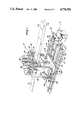
- FIG. 1 is a perspective view of the web splicing apparatus according to this invention.
- FIG. 2 is an end view of the web splicing apparatus shown in FIG. 1;
- FIG. 3 is a side elevation view with parts broken away for clarity
- FIG. 4 is a top plan view of the frame support plate.
- the reference number 10 generally designates the running web splicing apparatus according to this invention which is disposed to receive a running web 12 extending from a supply roll of web material (not shown) and pass such runnning web to a using machine (not shown), e.g. a hammermill.
- the web splicing apparatus 10 comprises, in general, a supporting frame 14 mounted on two rails 16 for reciprocable movement on and relative to a base 18.
- a web 22 extending from a full roll of web material may be positioned in the splicing device 20 preparatory to being spliced to the web portion of the severed end of the running web 12 when the supply roll nears depletion of web material.
- the frame 14 comprises a bottom wall 24 to which is secured, in any suitable manner, as for example by welding, a front wall 26 and rear wall 28.
- Opposite walls 30 and 32 are secured to front and rear walls 26 and 28.
- a top horizontal wall 34 is secured to the opposite side walls 30 and 32 and completes the frame.
- Front and rear walls 26 and 28 are dimensioned in width so that their respective upper edges are spaced from top wall 34 to thereby leave a space within which is mounted splicing device 20.
- An intermediate horizontal wall 35 is secured to the top edge of front and rear walls 26 and 28.
- the rectilinear pressurized fluid motors 36 are secured to top wall 34 and extend therethrough to splicing device 20.
- two rectilinear motors 37 are mounted on intermediate wall 35 (see FIG.
- the rails 16, which support frame 14, comprise spaced parallel pipes or rods 42 which are mounted on T-shaped brackets 44.
- Each of the brackets 44 is secured to base 18 by a plurality of holdown bolts 46 or may be secured to the base in any other suitable manner.
- Each of the rails 16 is slidably engaged by a pair of spaced shoes 48, preferrably of the ball bushing type, which are secured to the underside of bottom wall 24.
- the ball bushings 48 are of conventional construction and, as for example, may be ball bushings, model PB-OPN Pillow Block, Part No. NPBO-24-OPN, manufactured by Thomson Industries, Inc. of Manhasset, N.Y.
- Shoes 48 of the ball bushing type provide high load capacity together with low frictional resistance.
- Each shoe is secured, in any suitable manner such as by bolts 50, to bottom wall 24 of the frame 14.
- a biasing means 52 is connected between frame 14 and base 18.
- the biasing means 52 may comprise one or more bi-directional pressurized fluid, linear motors 54 and may be of the type disclosed in the U.S. Pat. No. 3,886,031 to Taitel.
- Each of the motors 54 comprises a cylinder-piston assembly mounted on base 18 between rails 16.
- the piston of the cylinder piston assemblies has attached thereto both ends of a cable 56.
- the cable 56 passes over a pulley 58 at each end of the cylinder of the piston-cylinder assembly and is connected to frame 14.
- Pressurized fluid is passed into the cylinder by means, not shown, so that a predetermined constant force is applied to the piston which force is transmitted through cable 56 to frame 14 so as to keep the tension on the web constant as the frame moves during the splicing operation and return.
- the frame, after splicing is returned to a starting position for a subsequent splicing operation.
- biasing means 52 may comprise one or more uni-directional, pressurized fluid, linear motors to bias the frame in a direction counter to the direction of travel of the running web so as to return the frame to its starting position.
- the splicing operation is initiated by appropriate activation of the control system (not shown).
- the frame 14 is drawn on rails 16 in the direction of the using machine (not shown) to provide the latter with web material during the time the running web travel is interrupted for splicing, thus permitting continuous operation of the using machine.
- frame 14 is returned to its starting position by motors 54 so that the apparatus is ready for a subsequent splicing operation.
- the present invention provides a novel running web splicing apparatus which is capable of splicing together webs of pulp material or relatively stiff material. It is a splicing apparatus which does not require a festoon assembly.
Abstract
The web splicing apparatus for connecting a running web extending and traveling between a supply of web material and a web using machine to the end portion of a new supply of web material comprises a frame to which is secured and supported a splicing device. The splicing device has web clamps and cutting members and functions to connect the severed end portion of a running web to the end portion of a new web. Two sets of slide shoes are secured to the frame to engage a pair of rails so that the frame is reciprocatively supported for movement in the direction of travel of a running web, when the splicing device is operative to effect a splice, to thereby supply web to the web using machine and moves in a direction counter to the direction of travel of the running web after the splicing is completed.
Description
This invention relates to a running web splicing apparatus of the type disclosed in the U.S. Pat. No. 4,157,934 to Ryan et al and Ryan, U.S. Pat. No. 4,374,576 which functions to connect a running web, extending between a completing roll of web material and a using machine, to the end of a new roll of web material without interruption of the feed of web to the using machine.
In heretofore known web lap or butt splicing apparatuses of the type disclosed in the aforementioned patents, a running web accumulator or festoon, as exemplified in the U.S. Pat. No. 3,886,031 to Taitel and Ryan, U.S. Pat. No. 4,374,576, is required to supply running web to the using machine, e.g. hammermill, during the period that the web is stopped for purposes of effecting the splice connection between the respective end portions of a depleting roll and new roll of web material. It has been found that the use of a festoon is not feasible for webs composed of filler absorbent material such as is used in diapers and sanitary napkins, known in the art as "pulp", before being fed into a hammermill where its density is decreased by a process known as "fluffing". A festoon is not practical because the rollers of the festoon around which the web of pulp has to be woven would be of exceptionally large size, as for example one foot in diameter, festoons requiring such large diameter rollers become impractically large in overall size. Also impractically large festoons would be required to accomodate webs of relatively stiff material as for example, cardboard and heavy paper of about 0.01 inches which must be woven around large diameter rollers to avoid fracture or tearing of the web. This problem of providing a using machine, such as a hammermill, with a supply of web of pulp material or relatively stiff material during splicing is solved by the web splicing machine of this invention.
Accordingly, an object of this invention is to provide a web splicing apparatus which is capable of providing a continuous running web to a using machine during splicing, but does not require a festoon. Another object of the present invention is to provide a splicing machine capable of handling a web of pulp or relatively stiff material.
Now, therefore, the present invention contemplates a novel web splicing apparatus for connecting a running web extending and traveling between a supply of web material, as for example, pulp, and a web using machine, as for example a hammermill, to the leading end portion of a new supply of web material, which comprises a frame and a splicing means, including web clamping means and web cutting means for clamping and cutting the running web and connecting the severed end portion of the running web to the leading end portion of a new web. The splicing means may function to butt or lap splice the webs together and may be of any suitable design such as is disclosed in the U.S. Pat. No. 3,886,031, to Taitel, Ryan, U.S. Pat. No. 4,190,483 and Ryan U.S. Pat. No. 4,374,576. The splicing means is attached to the frame. A support means is provided for supporting the frame for reciprocative movement along the line of travel of the running web so as to move in the direction of the travel of the running web during the splicing operation of the splicing means and thus provide a running web to the using machine and, thereafter, move in a direction counter to the direction of web travel after the splicing operation is completed.
In a narrower aspect of this invention, the means for supporting the frame includes a rail means and a rail engaging means secured to the frame.
A feature of this invention is a pair of spaced parallel rails disposed below the frame and two sets of slide shoes secured to the frame and constructed and arranged to suitably engage each of the rails.
The invention will now be more clearly understood when considered in connection with the accompanying drawings, in which:
FIG. 1 is a perspective view of the web splicing apparatus according to this invention;
FIG. 2 is an end view of the web splicing apparatus shown in FIG. 1;
FIG. 3 is a side elevation view with parts broken away for clarity; and
FIG. 4 is a top plan view of the frame support plate.
Now, referring to the drawings, more particularly FIG. 1, the reference number 10 generally designates the running web splicing apparatus according to this invention which is disposed to receive a running web 12 extending from a supply roll of web material (not shown) and pass such runnning web to a using machine (not shown), e.g. a hammermill.
The web splicing apparatus 10 comprises, in general, a supporting frame 14 mounted on two rails 16 for reciprocable movement on and relative to a base 18. A splicing device 20 of any suitable construction, such as disclosed in U.S. Pat. Nos. 3,886,031; 4,190,483 and 4,374,576, is carried by frame 14. A web 22 extending from a full roll of web material (not shown) may be positioned in the splicing device 20 preparatory to being spliced to the web portion of the severed end of the running web 12 when the supply roll nears depletion of web material.
The frame 14 comprises a bottom wall 24 to which is secured, in any suitable manner, as for example by welding, a front wall 26 and rear wall 28. Opposite walls 30 and 32 are secured to front and rear walls 26 and 28. A top horizontal wall 34 is secured to the opposite side walls 30 and 32 and completes the frame. Front and rear walls 26 and 28 are dimensioned in width so that their respective upper edges are spaced from top wall 34 to thereby leave a space within which is mounted splicing device 20. An intermediate horizontal wall 35 is secured to the top edge of front and rear walls 26 and 28. The rectilinear pressurized fluid motors 36 are secured to top wall 34 and extend therethrough to splicing device 20. Similarly, two rectilinear motors 37 are mounted on intermediate wall 35 (see FIG. 2) and are also connected to the splicing device. More particularly, motors 36 and 37 are connected so as to effect actuation of the clamping and cutting elements of splicing device 20. Electrical cables and/or pneumatic lines 38 (see FIG. 1) for effecting operation of splicing device 20 are secured to frame 14 and extend through a flexible sheath 40, through the base 18, to a source of electrical power and/or pressurized fluid (not shown). The electrical lines 38 form part of the control system (not shown) which provides for operational control of splicing device 20.
The rails 16, which support frame 14, comprise spaced parallel pipes or rods 42 which are mounted on T-shaped brackets 44. Each of the brackets 44 is secured to base 18 by a plurality of holdown bolts 46 or may be secured to the base in any other suitable manner. Each of the rails 16 is slidably engaged by a pair of spaced shoes 48, preferrably of the ball bushing type, which are secured to the underside of bottom wall 24. The ball bushings 48 are of conventional construction and, as for example, may be ball bushings, model PB-OPN Pillow Block, Part No. NPBO-24-OPN, manufactured by Thomson Industries, Inc. of Manhasset, N.Y. Shoes 48 of the ball bushing type provide high load capacity together with low frictional resistance. Each shoe is secured, in any suitable manner such as by bolts 50, to bottom wall 24 of the frame 14. To provide for the maintenance of a predetermined tension on running web 12 a biasing means 52 is connected between frame 14 and base 18.
The biasing means 52 may comprise one or more bi-directional pressurized fluid, linear motors 54 and may be of the type disclosed in the U.S. Pat. No. 3,886,031 to Taitel. Each of the motors 54 comprises a cylinder-piston assembly mounted on base 18 between rails 16. The piston of the cylinder piston assemblies has attached thereto both ends of a cable 56. The cable 56 passes over a pulley 58 at each end of the cylinder of the piston-cylinder assembly and is connected to frame 14. Pressurized fluid is passed into the cylinder by means, not shown, so that a predetermined constant force is applied to the piston which force is transmitted through cable 56 to frame 14 so as to keep the tension on the web constant as the frame moves during the splicing operation and return. The frame, after splicing, is returned to a starting position for a subsequent splicing operation.
In the event the running web is of a material of sufficient tensil strength so that the force applied to the running web 12 by the using machine during the splicing phase of operation can move the frame without tearing and thereby supply web material to the using machine during splicing, then biasing means 52 may comprise one or more uni-directional, pressurized fluid, linear motors to bias the frame in a direction counter to the direction of travel of the running web so as to return the frame to its starting position.
In operation of the running web splicing, apparatus 10, when it is desired to splice running web 12 to the leading end of web 22 of a full roll (not shown), the splicing operation is initiated by appropriate activation of the control system (not shown). When the running web 12 is clamped by splicing device 20 preparatory to being cut and secured to the leading end portion of web 22, the frame 14 is drawn on rails 16 in the direction of the using machine (not shown) to provide the latter with web material during the time the running web travel is interrupted for splicing, thus permitting continuous operation of the using machine. Upon completion of the splicing operation and the release of running web 12, frame 14 is returned to its starting position by motors 54 so that the apparatus is ready for a subsequent splicing operation.
It is believed now readily apparent that the present invention provides a novel running web splicing apparatus which is capable of splicing together webs of pulp material or relatively stiff material. It is a splicing apparatus which does not require a festoon assembly.
Although only one embodiment of the invention has been illustrated and described in detail, it is to be expressly understood that the invention is not limited thereto. Various changes can be made in the arrangement of parts without departing from the spirit and scope of the invention as the same will now be understood by those skilled in the art.
Claims (8)
1. A web splicing apparatus for connecting a running web extending and traveling between a supply of web material and a web using machine to the end portion of a new supply of web material comprising:
(a) a frame,
(b) splicing means, including web clamping and web cutting means for clamping and cutting the running web and connecting the severed end portion of the running web to the end portion of the new web, carried by said frame; and
(c) means for supporting said frame for reciprocative movement along the line of travel of the running web so as to move in the direction of the web travel during the splicing operation of said splicing means and thereby provide running web to the using machine and move in a direction counter to the direction of web travel after the splicing operation is completed.
2. The apparatus of claim 1 wherein the said means for supporting the frame for reciprocative movement includes rail means and rail engaging means secured to the frame.
3. The apparatus of claim 2 wherein said rail means comprises two spaced, parallel rails.
4. The apparatus of claim 3 wherein said rail engaging means comprises a plurality of slide shoes secured to the underside of said frame.
5. The apparatus of claim 3 wherein each of said rails are elongated cylindrical elements mounted on a T-shaped bracket.
6. The apparatus of claim 1 wherein a biasing means is connected to said frame to exert a biasing force on said frame in an opposite direction from the direction of travel of the running web.
7. The apparatus of claim 6 wherein said biasing means is pressurized fluid, cylinder-piston assembly.
8. The apparatus of claim 2 wherein said means for supporting the frame includes a base plate to which said rail means is attached.
Priority Applications (1)
| Application Number | Priority Date | Filing Date | Title |
|---|---|---|---|
| US07/167,524 US4776920A (en) | 1988-03-14 | 1988-03-14 | Running web splicing apparatus |
Applications Claiming Priority (1)
| Application Number | Priority Date | Filing Date | Title |
|---|---|---|---|
| US07/167,524 US4776920A (en) | 1988-03-14 | 1988-03-14 | Running web splicing apparatus |
Publications (1)
| Publication Number | Publication Date |
|---|---|
| US4776920A true US4776920A (en) | 1988-10-11 |
Family
ID=22607732
Family Applications (1)
| Application Number | Title | Priority Date | Filing Date |
|---|---|---|---|
| US07/167,524 Expired - Fee Related US4776920A (en) | 1988-03-14 | 1988-03-14 | Running web splicing apparatus |
Country Status (1)
| Country | Link |
|---|---|
| US (1) | US4776920A (en) |
Cited By (47)
| Publication number | Priority date | Publication date | Assignee | Title |
|---|---|---|---|---|
| US6050517A (en) * | 1998-09-22 | 2000-04-18 | Curt G. Joa | Counterbalanced web accumulator |
| US6059710A (en) * | 1998-12-24 | 2000-05-09 | Kimberly-Clark Worldwide, Inc. | Process for cutting of discrete components of a multi-component workpiece and depositing them with registration on a moving web of material |
| US6074333A (en) * | 1998-12-24 | 2000-06-13 | Kimberly-Clark Worldwide, Inc. | Machine for cutting discrete components of a multi-component workpiece and depositing them with registration on a moving web of material |
| US6165306A (en) * | 1998-06-01 | 2000-12-26 | Kimberly-Clark Worldwide, Inc. | Process and apparatus for cutting of discrete components of a multi-component workpiece and depositing them with registration on a moving web of material |
| US6737141B2 (en) | 2002-03-20 | 2004-05-18 | Kimberly-Clark Worldwide, Inc. | Usable splice for a stabilized absorbent and method for making the splice |
| US20040182498A1 (en) * | 2001-12-31 | 2004-09-23 | Kimberly-Clark Worldwide, Inc. | Process for making a splice for a stabilized absorbent |
| US7703599B2 (en) | 2004-04-19 | 2010-04-27 | Curt G. Joa, Inc. | Method and apparatus for reversing direction of an article |
| US7708849B2 (en) | 2004-04-20 | 2010-05-04 | Curt G. Joa, Inc. | Apparatus and method for cutting elastic strands between layers of carrier webs |
| US7770712B2 (en) | 2006-02-17 | 2010-08-10 | Curt G. Joa, Inc. | Article transfer and placement apparatus with active puck |
| US7780052B2 (en) | 2006-05-18 | 2010-08-24 | Curt G. Joa, Inc. | Trim removal system |
| US7811403B2 (en) | 2005-03-09 | 2010-10-12 | Curt G. Joa, Inc. | Transverse tab application method and apparatus |
| US7861756B2 (en) | 2004-04-20 | 2011-01-04 | Curt G. Joa, Inc. | Staggered cutting knife |
| US7909956B2 (en) | 2004-05-21 | 2011-03-22 | Curt G. Joa, Inc. | Method of producing a pants-type diaper |
| US7975584B2 (en) | 2007-02-21 | 2011-07-12 | Curt G. Joa, Inc. | Single transfer insert placement method and apparatus |
| US8007484B2 (en) | 2005-04-01 | 2011-08-30 | Curt G. Joa, Inc. | Pants type product and method of making the same |
| US8016972B2 (en) | 2007-05-09 | 2011-09-13 | Curt G. Joa, Inc. | Methods and apparatus for application of nested zero waste ear to traveling web |
| US8172977B2 (en) | 2009-04-06 | 2012-05-08 | Curt G. Joa, Inc. | Methods and apparatus for application of nested zero waste ear to traveling web |
| US8182624B2 (en) | 2008-03-12 | 2012-05-22 | Curt G. Joa, Inc. | Registered stretch laminate and methods for forming a registered stretch laminate |
| US20130037635A1 (en) * | 2011-08-09 | 2013-02-14 | Anirudh Singh | Process for defiberizing pulp |
| US8398793B2 (en) | 2007-07-20 | 2013-03-19 | Curt G. Joa, Inc. | Apparatus and method for minimizing waste and improving quality and production in web processing operations |
| US8417374B2 (en) | 2004-04-19 | 2013-04-09 | Curt G. Joa, Inc. | Method and apparatus for changing speed or direction of an article |
| US8460495B2 (en) | 2009-12-30 | 2013-06-11 | Curt G. Joa, Inc. | Method for producing absorbent article with stretch film side panel and application of intermittent discrete components of an absorbent article |
| USD684613S1 (en) | 2011-04-14 | 2013-06-18 | Curt G. Joa, Inc. | Sliding guard structure |
| US8656817B2 (en) | 2011-03-09 | 2014-02-25 | Curt G. Joa | Multi-profile die cutting assembly |
| US8663411B2 (en) | 2010-06-07 | 2014-03-04 | Curt G. Joa, Inc. | Apparatus and method for forming a pant-type diaper with refastenable side seams |
| US8673098B2 (en) | 2009-10-28 | 2014-03-18 | Curt G. Joa, Inc. | Method and apparatus for stretching segmented stretchable film and application of the segmented film to a moving web |
| USD703248S1 (en) | 2013-08-23 | 2014-04-22 | Curt G. Joa, Inc. | Ventilated vacuum commutation structure |
| USD703247S1 (en) | 2013-08-23 | 2014-04-22 | Curt G. Joa, Inc. | Ventilated vacuum commutation structure |
| USD703711S1 (en) | 2013-08-23 | 2014-04-29 | Curt G. Joa, Inc. | Ventilated vacuum communication structure |
| USD703712S1 (en) | 2013-08-23 | 2014-04-29 | Curt G. Joa, Inc. | Ventilated vacuum commutation structure |
| USD704237S1 (en) | 2013-08-23 | 2014-05-06 | Curt G. Joa, Inc. | Ventilated vacuum commutation structure |
| US8820380B2 (en) | 2011-07-21 | 2014-09-02 | Curt G. Joa, Inc. | Differential speed shafted machines and uses therefor, including discontinuous and continuous side by side bonding |
| US9089453B2 (en) | 2009-12-30 | 2015-07-28 | Curt G. Joa, Inc. | Method for producing absorbent article with stretch film side panel and application of intermittent discrete components of an absorbent article |
| US9283683B2 (en) | 2013-07-24 | 2016-03-15 | Curt G. Joa, Inc. | Ventilated vacuum commutation structures |
| US9289329B1 (en) | 2013-12-05 | 2016-03-22 | Curt G. Joa, Inc. | Method for producing pant type diapers |
| US9387131B2 (en) | 2007-07-20 | 2016-07-12 | Curt G. Joa, Inc. | Apparatus and method for minimizing waste and improving quality and production in web processing operations by automated threading and re-threading of web materials |
| US9433538B2 (en) | 2006-05-18 | 2016-09-06 | Curt G. Joa, Inc. | Methods and apparatus for application of nested zero waste ear to traveling web and formation of articles using a dual cut slip unit |
| US9550306B2 (en) | 2007-02-21 | 2017-01-24 | Curt G. Joa, Inc. | Single transfer insert placement and apparatus with cross-direction insert placement control |
| US9566193B2 (en) | 2011-02-25 | 2017-02-14 | Curt G. Joa, Inc. | Methods and apparatus for forming disposable products at high speeds with small machine footprint |
| US9603752B2 (en) | 2010-08-05 | 2017-03-28 | Curt G. Joa, Inc. | Apparatus and method for minimizing waste and improving quality and production in web processing operations by automatic cuff defect correction |
| US9622918B2 (en) | 2006-05-18 | 2017-04-18 | Curt G. Joe, Inc. | Methods and apparatus for application of nested zero waste ear to traveling web |
| US9809414B2 (en) | 2012-04-24 | 2017-11-07 | Curt G. Joa, Inc. | Elastic break brake apparatus and method for minimizing broken elastic rethreading |
| US9944487B2 (en) | 2007-02-21 | 2018-04-17 | Curt G. Joa, Inc. | Single transfer insert placement method and apparatus |
| US10167156B2 (en) | 2015-07-24 | 2019-01-01 | Curt G. Joa, Inc. | Vacuum commutation apparatus and methods |
| US10456302B2 (en) | 2006-05-18 | 2019-10-29 | Curt G. Joa, Inc. | Methods and apparatus for application of nested zero waste ear to traveling web |
| US10751220B2 (en) | 2012-02-20 | 2020-08-25 | Curt G. Joa, Inc. | Method of forming bonds between discrete components of disposable articles |
| US11737930B2 (en) | 2020-02-27 | 2023-08-29 | Curt G. Joa, Inc. | Configurable single transfer insert placement method and apparatus |
Citations (5)
| Publication number | Priority date | Publication date | Assignee | Title |
|---|---|---|---|---|
| US3537939A (en) * | 1967-05-01 | 1970-11-03 | Nat Gypsum Co | Splicing apparatus for continuously advancing webs |
| US3920502A (en) * | 1973-03-07 | 1975-11-18 | Rengo Co Ltd | Apparatus for splicing paper rolls |
| US4490199A (en) * | 1982-07-01 | 1984-12-25 | Allied Corporation | Method and apparatus for splicing polymeric webs |
| US4555281A (en) * | 1983-10-28 | 1985-11-26 | G.D Societa' Per Azioni | Method for automatically setting and joining reel-fed label strips or similar |
| US4561924A (en) * | 1982-10-05 | 1985-12-31 | Hope Henry F | Automatic material splicer for photographic materials |
-
1988
- 1988-03-14 US US07/167,524 patent/US4776920A/en not_active Expired - Fee Related
Patent Citations (5)
| Publication number | Priority date | Publication date | Assignee | Title |
|---|---|---|---|---|
| US3537939A (en) * | 1967-05-01 | 1970-11-03 | Nat Gypsum Co | Splicing apparatus for continuously advancing webs |
| US3920502A (en) * | 1973-03-07 | 1975-11-18 | Rengo Co Ltd | Apparatus for splicing paper rolls |
| US4490199A (en) * | 1982-07-01 | 1984-12-25 | Allied Corporation | Method and apparatus for splicing polymeric webs |
| US4561924A (en) * | 1982-10-05 | 1985-12-31 | Hope Henry F | Automatic material splicer for photographic materials |
| US4555281A (en) * | 1983-10-28 | 1985-11-26 | G.D Societa' Per Azioni | Method for automatically setting and joining reel-fed label strips or similar |
Cited By (65)
| Publication number | Priority date | Publication date | Assignee | Title |
|---|---|---|---|---|
| US6165306A (en) * | 1998-06-01 | 2000-12-26 | Kimberly-Clark Worldwide, Inc. | Process and apparatus for cutting of discrete components of a multi-component workpiece and depositing them with registration on a moving web of material |
| US6520236B1 (en) | 1998-06-01 | 2003-02-18 | Kimberly-Clark Worldwide, Inc. | Process and apparatus for cutting of discrete components of a multi-component workpiece and depositing them with registration on a moving web of material |
| US6527902B1 (en) | 1998-06-01 | 2003-03-04 | Kimberly-Clark Worldwide, Inc. | Process and apparatus for cutting of discrete components of a multi-component workpiece and depositing them with registration on a moving web of material |
| US6050517A (en) * | 1998-09-22 | 2000-04-18 | Curt G. Joa | Counterbalanced web accumulator |
| US6059710A (en) * | 1998-12-24 | 2000-05-09 | Kimberly-Clark Worldwide, Inc. | Process for cutting of discrete components of a multi-component workpiece and depositing them with registration on a moving web of material |
| US6074333A (en) * | 1998-12-24 | 2000-06-13 | Kimberly-Clark Worldwide, Inc. | Machine for cutting discrete components of a multi-component workpiece and depositing them with registration on a moving web of material |
| US20040185214A1 (en) * | 2001-12-31 | 2004-09-23 | Kimberly-Clark Worldwide, Inc. | Personal care absorbent article having spliced absorbent material |
| US20040182498A1 (en) * | 2001-12-31 | 2004-09-23 | Kimberly-Clark Worldwide, Inc. | Process for making a splice for a stabilized absorbent |
| US6863945B2 (en) | 2001-12-31 | 2005-03-08 | Kimberly-Clark Worldwide, Inc. | Usable splice for a stabilized absorbent |
| US7273646B2 (en) | 2001-12-31 | 2007-09-25 | Kimberly-Clark Worldwide, Inc. | Personal care absorbent article having spliced absorbent material |
| US7311792B2 (en) | 2001-12-31 | 2007-12-25 | Kimberly-Clark Worldwide, Inc. | Process for making a splice for a stabilized absorbent |
| US6737141B2 (en) | 2002-03-20 | 2004-05-18 | Kimberly-Clark Worldwide, Inc. | Usable splice for a stabilized absorbent and method for making the splice |
| US7703599B2 (en) | 2004-04-19 | 2010-04-27 | Curt G. Joa, Inc. | Method and apparatus for reversing direction of an article |
| US8417374B2 (en) | 2004-04-19 | 2013-04-09 | Curt G. Joa, Inc. | Method and apparatus for changing speed or direction of an article |
| US7861756B2 (en) | 2004-04-20 | 2011-01-04 | Curt G. Joa, Inc. | Staggered cutting knife |
| US7708849B2 (en) | 2004-04-20 | 2010-05-04 | Curt G. Joa, Inc. | Apparatus and method for cutting elastic strands between layers of carrier webs |
| US8557077B2 (en) | 2004-05-21 | 2013-10-15 | Curt G. Joa, Inc. | Method of producing a pants-type diaper |
| US7909956B2 (en) | 2004-05-21 | 2011-03-22 | Curt G. Joa, Inc. | Method of producing a pants-type diaper |
| US7811403B2 (en) | 2005-03-09 | 2010-10-12 | Curt G. Joa, Inc. | Transverse tab application method and apparatus |
| US8007484B2 (en) | 2005-04-01 | 2011-08-30 | Curt G. Joa, Inc. | Pants type product and method of making the same |
| US7770712B2 (en) | 2006-02-17 | 2010-08-10 | Curt G. Joa, Inc. | Article transfer and placement apparatus with active puck |
| US7780052B2 (en) | 2006-05-18 | 2010-08-24 | Curt G. Joa, Inc. | Trim removal system |
| US9433538B2 (en) | 2006-05-18 | 2016-09-06 | Curt G. Joa, Inc. | Methods and apparatus for application of nested zero waste ear to traveling web and formation of articles using a dual cut slip unit |
| US9622918B2 (en) | 2006-05-18 | 2017-04-18 | Curt G. Joe, Inc. | Methods and apparatus for application of nested zero waste ear to traveling web |
| US8293056B2 (en) | 2006-05-18 | 2012-10-23 | Curt G. Joa, Inc. | Trim removal system |
| US10456302B2 (en) | 2006-05-18 | 2019-10-29 | Curt G. Joa, Inc. | Methods and apparatus for application of nested zero waste ear to traveling web |
| US9944487B2 (en) | 2007-02-21 | 2018-04-17 | Curt G. Joa, Inc. | Single transfer insert placement method and apparatus |
| US7975584B2 (en) | 2007-02-21 | 2011-07-12 | Curt G. Joa, Inc. | Single transfer insert placement method and apparatus |
| US8794115B2 (en) | 2007-02-21 | 2014-08-05 | Curt G. Joa, Inc. | Single transfer insert placement method and apparatus |
| US10266362B2 (en) | 2007-02-21 | 2019-04-23 | Curt G. Joa, Inc. | Single transfer insert placement method and apparatus |
| US9950439B2 (en) | 2007-02-21 | 2018-04-24 | Curt G. Joa, Inc. | Single transfer insert placement method and apparatus with cross-direction insert placement control |
| US9550306B2 (en) | 2007-02-21 | 2017-01-24 | Curt G. Joa, Inc. | Single transfer insert placement and apparatus with cross-direction insert placement control |
| US8016972B2 (en) | 2007-05-09 | 2011-09-13 | Curt G. Joa, Inc. | Methods and apparatus for application of nested zero waste ear to traveling web |
| US9387131B2 (en) | 2007-07-20 | 2016-07-12 | Curt G. Joa, Inc. | Apparatus and method for minimizing waste and improving quality and production in web processing operations by automated threading and re-threading of web materials |
| US8398793B2 (en) | 2007-07-20 | 2013-03-19 | Curt G. Joa, Inc. | Apparatus and method for minimizing waste and improving quality and production in web processing operations |
| US8182624B2 (en) | 2008-03-12 | 2012-05-22 | Curt G. Joa, Inc. | Registered stretch laminate and methods for forming a registered stretch laminate |
| US10702428B2 (en) | 2009-04-06 | 2020-07-07 | Curt G. Joa, Inc. | Methods and apparatus for application of nested zero waste ear to traveling web |
| US8172977B2 (en) | 2009-04-06 | 2012-05-08 | Curt G. Joa, Inc. | Methods and apparatus for application of nested zero waste ear to traveling web |
| US8673098B2 (en) | 2009-10-28 | 2014-03-18 | Curt G. Joa, Inc. | Method and apparatus for stretching segmented stretchable film and application of the segmented film to a moving web |
| US9089453B2 (en) | 2009-12-30 | 2015-07-28 | Curt G. Joa, Inc. | Method for producing absorbent article with stretch film side panel and application of intermittent discrete components of an absorbent article |
| US8460495B2 (en) | 2009-12-30 | 2013-06-11 | Curt G. Joa, Inc. | Method for producing absorbent article with stretch film side panel and application of intermittent discrete components of an absorbent article |
| US8663411B2 (en) | 2010-06-07 | 2014-03-04 | Curt G. Joa, Inc. | Apparatus and method for forming a pant-type diaper with refastenable side seams |
| USRE48182E1 (en) | 2010-08-05 | 2020-09-01 | Curt G. Joa, Inc. | Apparatus and method for minimizing waste and improving quality and production in web processing operations by automatic cuff defect correction |
| US9603752B2 (en) | 2010-08-05 | 2017-03-28 | Curt G. Joa, Inc. | Apparatus and method for minimizing waste and improving quality and production in web processing operations by automatic cuff defect correction |
| US9566193B2 (en) | 2011-02-25 | 2017-02-14 | Curt G. Joa, Inc. | Methods and apparatus for forming disposable products at high speeds with small machine footprint |
| US9907706B2 (en) | 2011-02-25 | 2018-03-06 | Curt G. Joa, Inc. | Methods and apparatus for forming disposable products at high speeds with small machine footprint |
| US8656817B2 (en) | 2011-03-09 | 2014-02-25 | Curt G. Joa | Multi-profile die cutting assembly |
| USD684613S1 (en) | 2011-04-14 | 2013-06-18 | Curt G. Joa, Inc. | Sliding guard structure |
| US8820380B2 (en) | 2011-07-21 | 2014-09-02 | Curt G. Joa, Inc. | Differential speed shafted machines and uses therefor, including discontinuous and continuous side by side bonding |
| US20130037635A1 (en) * | 2011-08-09 | 2013-02-14 | Anirudh Singh | Process for defiberizing pulp |
| US10751220B2 (en) | 2012-02-20 | 2020-08-25 | Curt G. Joa, Inc. | Method of forming bonds between discrete components of disposable articles |
| US9908739B2 (en) | 2012-04-24 | 2018-03-06 | Curt G. Joa, Inc. | Apparatus and method for applying parallel flared elastics to disposable products and disposable products containing parallel flared elastics |
| US9809414B2 (en) | 2012-04-24 | 2017-11-07 | Curt G. Joa, Inc. | Elastic break brake apparatus and method for minimizing broken elastic rethreading |
| US11034543B2 (en) | 2012-04-24 | 2021-06-15 | Curt G. Joa, Inc. | Apparatus and method for applying parallel flared elastics to disposable products and disposable products containing parallel flared elastics |
| US9283683B2 (en) | 2013-07-24 | 2016-03-15 | Curt G. Joa, Inc. | Ventilated vacuum commutation structures |
| USD704237S1 (en) | 2013-08-23 | 2014-05-06 | Curt G. Joa, Inc. | Ventilated vacuum commutation structure |
| USD703248S1 (en) | 2013-08-23 | 2014-04-22 | Curt G. Joa, Inc. | Ventilated vacuum commutation structure |
| USD703711S1 (en) | 2013-08-23 | 2014-04-29 | Curt G. Joa, Inc. | Ventilated vacuum communication structure |
| USD703247S1 (en) | 2013-08-23 | 2014-04-22 | Curt G. Joa, Inc. | Ventilated vacuum commutation structure |
| USD703712S1 (en) | 2013-08-23 | 2014-04-29 | Curt G. Joa, Inc. | Ventilated vacuum commutation structure |
| US9289329B1 (en) | 2013-12-05 | 2016-03-22 | Curt G. Joa, Inc. | Method for producing pant type diapers |
| US10167156B2 (en) | 2015-07-24 | 2019-01-01 | Curt G. Joa, Inc. | Vacuum commutation apparatus and methods |
| US10633207B2 (en) | 2015-07-24 | 2020-04-28 | Curt G. Joa, Inc. | Vacuum commutation apparatus and methods |
| US10494216B2 (en) | 2015-07-24 | 2019-12-03 | Curt G. Joa, Inc. | Vacuum communication apparatus and methods |
| US11737930B2 (en) | 2020-02-27 | 2023-08-29 | Curt G. Joa, Inc. | Configurable single transfer insert placement method and apparatus |
Similar Documents
| Publication | Publication Date | Title |
|---|---|---|
| US4776920A (en) | Running web splicing apparatus | |
| US3841944A (en) | Web splicing apparatus | |
| CN102295177B (en) | Splicing device to join together two web materials, unwinding device comprising said splicing device | |
| US3858819A (en) | Web supply apparatus | |
| CA2025552C (en) | Paper web threading apparatus for rotary printing press | |
| DE69818738T2 (en) | Unwinding system with central drive | |
| US5679195A (en) | Web splicing apparatus | |
| CA2049006C (en) | System for joining webs of material | |
| US4564413A (en) | Sheet splicer | |
| US20040084133A1 (en) | Splicing device for splicing two web materials together, unwinder comprising said slicing device and relative method | |
| US4995936A (en) | Continuous web splicing machine | |
| DE59005147D1 (en) | Flying change of the winding roll in a splicer. | |
| EP1163178B1 (en) | Device for connecting material webs | |
| GB1569886A (en) | Splicing webs of sheet material | |
| US5447296A (en) | Cloth spreading system | |
| USRE29365E (en) | Web supply apparatus | |
| US4792103A (en) | Device for splicing two webs of material each originating from a roll | |
| US4509733A (en) | Multiple paper web guiding and combining apparatus for combination with rotary printing machine and folding device | |
| CN109689547B (en) | Feeding unit of a towel converting machine for converting a double web of towels | |
| JP3517195B2 (en) | Adhesive tape connection device and method | |
| GB2190930A (en) | Fabric spreading and cutting | |
| CN213445626U (en) | Diaphragm slitting device | |
| JPH0624704B2 (en) | Improved joining tape and its manufacturing method | |
| JPH0228457A (en) | Lap-joint method and device of paper tape for manufacturing tape,particularly corrugated board paper | |
| CA1263076A (en) | Gluing means in a continuous action web reeler |
Legal Events
| Date | Code | Title | Description |
|---|---|---|---|
| AS | Assignment |
Owner name: COMPENSATING TENSION CONTROLS, INC., A CORP. Free format text: ASSIGNMENT OF ASSIGNORS INTEREST.;ASSIGNOR:RYAN, RALPH L.;REEL/FRAME:004881/0164 Effective date: 19880309 |
|
| FEPP | Fee payment procedure |
Free format text: PAYOR NUMBER ASSIGNED (ORIGINAL EVENT CODE: ASPN); ENTITY STATUS OF PATENT OWNER: SMALL ENTITY |
|
| FPAY | Fee payment |
Year of fee payment: 4 |
|
| REMI | Maintenance fee reminder mailed | ||
| LAPS | Lapse for failure to pay maintenance fees | ||
| FP | Lapsed due to failure to pay maintenance fee |
Effective date: 19961016 |
|
| STCH | Information on status: patent discontinuation |
Free format text: PATENT EXPIRED DUE TO NONPAYMENT OF MAINTENANCE FEES UNDER 37 CFR 1.362 |