US9808357B2 - Reactive layer control system for prosthetic and orthotic devices - Google Patents
Reactive layer control system for prosthetic and orthotic devices Download PDFInfo
- Publication number
- US9808357B2 US9808357B2 US12/523,710 US52371008A US9808357B2 US 9808357 B2 US9808357 B2 US 9808357B2 US 52371008 A US52371008 A US 52371008A US 9808357 B2 US9808357 B2 US 9808357B2
- Authority
- US
- United States
- Prior art keywords
- joint
- actuator
- torque
- gain
- motion
- Prior art date
- Legal status (The legal status is an assumption and is not a legal conclusion. Google has not performed a legal analysis and makes no representation as to the accuracy of the status listed.)
- Active, expires
Links
Images


Classifications
-
- A—HUMAN NECESSITIES
- A61—MEDICAL OR VETERINARY SCIENCE; HYGIENE
- A61F—FILTERS IMPLANTABLE INTO BLOOD VESSELS; PROSTHESES; DEVICES PROVIDING PATENCY TO, OR PREVENTING COLLAPSING OF, TUBULAR STRUCTURES OF THE BODY, e.g. STENTS; ORTHOPAEDIC, NURSING OR CONTRACEPTIVE DEVICES; FOMENTATION; TREATMENT OR PROTECTION OF EYES OR EARS; BANDAGES, DRESSINGS OR ABSORBENT PADS; FIRST-AID KITS
- A61F2/00—Filters implantable into blood vessels; Prostheses, i.e. artificial substitutes or replacements for parts of the body; Appliances for connecting them with the body; Devices providing patency to, or preventing collapsing of, tubular structures of the body, e.g. stents
- A61F2/50—Prostheses not implantable in the body
- A61F2/68—Operating or control means
- A61F2/70—Operating or control means electrical
-
- A—HUMAN NECESSITIES
- A61—MEDICAL OR VETERINARY SCIENCE; HYGIENE
- A61F—FILTERS IMPLANTABLE INTO BLOOD VESSELS; PROSTHESES; DEVICES PROVIDING PATENCY TO, OR PREVENTING COLLAPSING OF, TUBULAR STRUCTURES OF THE BODY, e.g. STENTS; ORTHOPAEDIC, NURSING OR CONTRACEPTIVE DEVICES; FOMENTATION; TREATMENT OR PROTECTION OF EYES OR EARS; BANDAGES, DRESSINGS OR ABSORBENT PADS; FIRST-AID KITS
- A61F2/00—Filters implantable into blood vessels; Prostheses, i.e. artificial substitutes or replacements for parts of the body; Appliances for connecting them with the body; Devices providing patency to, or preventing collapsing of, tubular structures of the body, e.g. stents
- A61F2/50—Prostheses not implantable in the body
- A61F2/60—Artificial legs or feet or parts thereof
- A61F2/64—Knee joints
-
- A—HUMAN NECESSITIES
- A61—MEDICAL OR VETERINARY SCIENCE; HYGIENE
- A61F—FILTERS IMPLANTABLE INTO BLOOD VESSELS; PROSTHESES; DEVICES PROVIDING PATENCY TO, OR PREVENTING COLLAPSING OF, TUBULAR STRUCTURES OF THE BODY, e.g. STENTS; ORTHOPAEDIC, NURSING OR CONTRACEPTIVE DEVICES; FOMENTATION; TREATMENT OR PROTECTION OF EYES OR EARS; BANDAGES, DRESSINGS OR ABSORBENT PADS; FIRST-AID KITS
- A61F2/00—Filters implantable into blood vessels; Prostheses, i.e. artificial substitutes or replacements for parts of the body; Appliances for connecting them with the body; Devices providing patency to, or preventing collapsing of, tubular structures of the body, e.g. stents
- A61F2/50—Prostheses not implantable in the body
- A61F2/68—Operating or control means
-
- A—HUMAN NECESSITIES
- A61—MEDICAL OR VETERINARY SCIENCE; HYGIENE
- A61F—FILTERS IMPLANTABLE INTO BLOOD VESSELS; PROSTHESES; DEVICES PROVIDING PATENCY TO, OR PREVENTING COLLAPSING OF, TUBULAR STRUCTURES OF THE BODY, e.g. STENTS; ORTHOPAEDIC, NURSING OR CONTRACEPTIVE DEVICES; FOMENTATION; TREATMENT OR PROTECTION OF EYES OR EARS; BANDAGES, DRESSINGS OR ABSORBENT PADS; FIRST-AID KITS
- A61F2/00—Filters implantable into blood vessels; Prostheses, i.e. artificial substitutes or replacements for parts of the body; Appliances for connecting them with the body; Devices providing patency to, or preventing collapsing of, tubular structures of the body, e.g. stents
- A61F2/50—Prostheses not implantable in the body
- A61F2002/5016—Prostheses not implantable in the body adjustable
- A61F2002/5033—Prostheses not implantable in the body adjustable for adjusting damping
-
- A—HUMAN NECESSITIES
- A61—MEDICAL OR VETERINARY SCIENCE; HYGIENE
- A61F—FILTERS IMPLANTABLE INTO BLOOD VESSELS; PROSTHESES; DEVICES PROVIDING PATENCY TO, OR PREVENTING COLLAPSING OF, TUBULAR STRUCTURES OF THE BODY, e.g. STENTS; ORTHOPAEDIC, NURSING OR CONTRACEPTIVE DEVICES; FOMENTATION; TREATMENT OR PROTECTION OF EYES OR EARS; BANDAGES, DRESSINGS OR ABSORBENT PADS; FIRST-AID KITS
- A61F2/00—Filters implantable into blood vessels; Prostheses, i.e. artificial substitutes or replacements for parts of the body; Appliances for connecting them with the body; Devices providing patency to, or preventing collapsing of, tubular structures of the body, e.g. stents
- A61F2/50—Prostheses not implantable in the body
- A61F2/68—Operating or control means
- A61F2002/6818—Operating or control means for braking
-
- A—HUMAN NECESSITIES
- A61—MEDICAL OR VETERINARY SCIENCE; HYGIENE
- A61F—FILTERS IMPLANTABLE INTO BLOOD VESSELS; PROSTHESES; DEVICES PROVIDING PATENCY TO, OR PREVENTING COLLAPSING OF, TUBULAR STRUCTURES OF THE BODY, e.g. STENTS; ORTHOPAEDIC, NURSING OR CONTRACEPTIVE DEVICES; FOMENTATION; TREATMENT OR PROTECTION OF EYES OR EARS; BANDAGES, DRESSINGS OR ABSORBENT PADS; FIRST-AID KITS
- A61F2/00—Filters implantable into blood vessels; Prostheses, i.e. artificial substitutes or replacements for parts of the body; Appliances for connecting them with the body; Devices providing patency to, or preventing collapsing of, tubular structures of the body, e.g. stents
- A61F2/50—Prostheses not implantable in the body
- A61F2/68—Operating or control means
- A61F2/70—Operating or control means electrical
- A61F2002/701—Operating or control means electrical operated by electrically controlled means, e.g. solenoids or torque motors
-
- A—HUMAN NECESSITIES
- A61—MEDICAL OR VETERINARY SCIENCE; HYGIENE
- A61F—FILTERS IMPLANTABLE INTO BLOOD VESSELS; PROSTHESES; DEVICES PROVIDING PATENCY TO, OR PREVENTING COLLAPSING OF, TUBULAR STRUCTURES OF THE BODY, e.g. STENTS; ORTHOPAEDIC, NURSING OR CONTRACEPTIVE DEVICES; FOMENTATION; TREATMENT OR PROTECTION OF EYES OR EARS; BANDAGES, DRESSINGS OR ABSORBENT PADS; FIRST-AID KITS
- A61F2/00—Filters implantable into blood vessels; Prostheses, i.e. artificial substitutes or replacements for parts of the body; Appliances for connecting them with the body; Devices providing patency to, or preventing collapsing of, tubular structures of the body, e.g. stents
- A61F2/50—Prostheses not implantable in the body
- A61F2/68—Operating or control means
- A61F2/70—Operating or control means electrical
- A61F2002/704—Operating or control means electrical computer-controlled, e.g. robotic control
-
- A—HUMAN NECESSITIES
- A61—MEDICAL OR VETERINARY SCIENCE; HYGIENE
- A61F—FILTERS IMPLANTABLE INTO BLOOD VESSELS; PROSTHESES; DEVICES PROVIDING PATENCY TO, OR PREVENTING COLLAPSING OF, TUBULAR STRUCTURES OF THE BODY, e.g. STENTS; ORTHOPAEDIC, NURSING OR CONTRACEPTIVE DEVICES; FOMENTATION; TREATMENT OR PROTECTION OF EYES OR EARS; BANDAGES, DRESSINGS OR ABSORBENT PADS; FIRST-AID KITS
- A61F2/00—Filters implantable into blood vessels; Prostheses, i.e. artificial substitutes or replacements for parts of the body; Appliances for connecting them with the body; Devices providing patency to, or preventing collapsing of, tubular structures of the body, e.g. stents
- A61F2/50—Prostheses not implantable in the body
- A61F2/76—Means for assembling, fitting or testing prostheses, e.g. for measuring or balancing, e.g. alignment means
- A61F2002/7615—Measuring means
- A61F2002/762—Measuring means for measuring dimensions, e.g. a distance
-
- A—HUMAN NECESSITIES
- A61—MEDICAL OR VETERINARY SCIENCE; HYGIENE
- A61F—FILTERS IMPLANTABLE INTO BLOOD VESSELS; PROSTHESES; DEVICES PROVIDING PATENCY TO, OR PREVENTING COLLAPSING OF, TUBULAR STRUCTURES OF THE BODY, e.g. STENTS; ORTHOPAEDIC, NURSING OR CONTRACEPTIVE DEVICES; FOMENTATION; TREATMENT OR PROTECTION OF EYES OR EARS; BANDAGES, DRESSINGS OR ABSORBENT PADS; FIRST-AID KITS
- A61F2/00—Filters implantable into blood vessels; Prostheses, i.e. artificial substitutes or replacements for parts of the body; Appliances for connecting them with the body; Devices providing patency to, or preventing collapsing of, tubular structures of the body, e.g. stents
- A61F2/50—Prostheses not implantable in the body
- A61F2/76—Means for assembling, fitting or testing prostheses, e.g. for measuring or balancing, e.g. alignment means
- A61F2002/7615—Measuring means
- A61F2002/7625—Measuring means for measuring angular position
-
- A—HUMAN NECESSITIES
- A61—MEDICAL OR VETERINARY SCIENCE; HYGIENE
- A61F—FILTERS IMPLANTABLE INTO BLOOD VESSELS; PROSTHESES; DEVICES PROVIDING PATENCY TO, OR PREVENTING COLLAPSING OF, TUBULAR STRUCTURES OF THE BODY, e.g. STENTS; ORTHOPAEDIC, NURSING OR CONTRACEPTIVE DEVICES; FOMENTATION; TREATMENT OR PROTECTION OF EYES OR EARS; BANDAGES, DRESSINGS OR ABSORBENT PADS; FIRST-AID KITS
- A61F2/00—Filters implantable into blood vessels; Prostheses, i.e. artificial substitutes or replacements for parts of the body; Appliances for connecting them with the body; Devices providing patency to, or preventing collapsing of, tubular structures of the body, e.g. stents
- A61F2/50—Prostheses not implantable in the body
- A61F2/76—Means for assembling, fitting or testing prostheses, e.g. for measuring or balancing, e.g. alignment means
- A61F2002/7615—Measuring means
- A61F2002/7635—Measuring means for measuring force, pressure or mechanical tension
-
- A—HUMAN NECESSITIES
- A61—MEDICAL OR VETERINARY SCIENCE; HYGIENE
- A61F—FILTERS IMPLANTABLE INTO BLOOD VESSELS; PROSTHESES; DEVICES PROVIDING PATENCY TO, OR PREVENTING COLLAPSING OF, TUBULAR STRUCTURES OF THE BODY, e.g. STENTS; ORTHOPAEDIC, NURSING OR CONTRACEPTIVE DEVICES; FOMENTATION; TREATMENT OR PROTECTION OF EYES OR EARS; BANDAGES, DRESSINGS OR ABSORBENT PADS; FIRST-AID KITS
- A61F2/00—Filters implantable into blood vessels; Prostheses, i.e. artificial substitutes or replacements for parts of the body; Appliances for connecting them with the body; Devices providing patency to, or preventing collapsing of, tubular structures of the body, e.g. stents
- A61F2/50—Prostheses not implantable in the body
- A61F2/76—Means for assembling, fitting or testing prostheses, e.g. for measuring or balancing, e.g. alignment means
- A61F2002/7615—Measuring means
- A61F2002/764—Measuring means for measuring acceleration
-
- A—HUMAN NECESSITIES
- A61—MEDICAL OR VETERINARY SCIENCE; HYGIENE
- A61F—FILTERS IMPLANTABLE INTO BLOOD VESSELS; PROSTHESES; DEVICES PROVIDING PATENCY TO, OR PREVENTING COLLAPSING OF, TUBULAR STRUCTURES OF THE BODY, e.g. STENTS; ORTHOPAEDIC, NURSING OR CONTRACEPTIVE DEVICES; FOMENTATION; TREATMENT OR PROTECTION OF EYES OR EARS; BANDAGES, DRESSINGS OR ABSORBENT PADS; FIRST-AID KITS
- A61F2/00—Filters implantable into blood vessels; Prostheses, i.e. artificial substitutes or replacements for parts of the body; Appliances for connecting them with the body; Devices providing patency to, or preventing collapsing of, tubular structures of the body, e.g. stents
- A61F2/50—Prostheses not implantable in the body
- A61F2/76—Means for assembling, fitting or testing prostheses, e.g. for measuring or balancing, e.g. alignment means
- A61F2002/7615—Measuring means
- A61F2002/7645—Measuring means for measuring torque, e.g. hinge or turning moment, moment of force
Definitions
- the present invention relates to a reactive layer control system for prosthetic and orthotic devices.
- Prosthetic and orthotic devices for restoring or replacing lost lower-limb functions have been available for many years. Until recently, both types of devices were found as purely mechanical linkages making advantageous usage of simple mechanisms in order to preclude knee buckling in level walking stance phase, while still ensuring some form of swing motion during the aerial phase. While this type of device was shown to be fairly efficient in restoring the structural aspects of the lower-limb role in gait, their incapacity to properly sustain the wide variety of lower-limb dynamics associated with the various gait locomotion activities performed on a daily basis appeared as a sufficient limitation to sustain the development of more advanced devices.
- common prosthetic or orthotic devices lack the ability to properly reproduce natural knee joint behavior and dynamic properties when used in a context that significantly differs from typical locomotion tasks. While generation of proper joint dynamics during cyclical locomotion portions ensure high symbiosis and user benefits, limitations observed in the capacity to reproduce natural joint compliance, or motions, in either non-locomotor or non-cyclical tasks significantly affect orthotic, or prosthetic, device usability and, accordingly, associated user benefits.
- variable gain impedance controller for use in a control system for controlling a prosthetic or orthotic apparatus provided with a joint, the controller comprising:
- variable gain impedance controller for use in a control system for controlling a motorized prosthetic or orthotic apparatus provided with a joint, the controller comprising:
- variable gain impedance controller for use in a control system for controlling a motorized prosthetic or orthotic apparatus provided with a joint, the controller comprising:
- FIG. 1 is a block diagram of the interaction between various control system layers and major building blocks of a motorized prosthetic and/or orthotic device
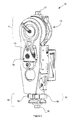
- FIG. 2 is an isometric view of a motorized knee prosthesis
- FIG. 3 is a schematic representation of the lower-limb mechanical power exchange during ground contact phase
- FIG. 4 is a schematic representation of the lower-limb mechanical power exchange during aerial phase
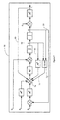
- FIG. 5 is a block diagram of a variable gains impedance controller basic formulation
- FIG. 6 is a flow diagram of a gain scheduling mechanism and associated reference engine
- FIG. 7 is a block diagram of a variable gains impedance controller with breaking feedback transfer function
- FIG. 8 is a chart illustrating the braking reactive behavior activation subspace.
- FIG. 9 is a block diagram of a variable gains impedance controller with energy injection feedforward function.
- the non-limitative illustrative embodiment of the present invention provides a reactive layer control system for motorized prosthetic or orthotic devices for restoring lost locomotor functions, or facilitate gait re-education resulting from various pathologies occurrence.
- the reactive layer control system is part of a multi-layered controller and is based on impedance control, which directly manages a subset of lower-limb joint behaviors allowing the sustaining of highly efficient mechanical power exchanges between the user and a prosthetic or orthotic apparatus.
- FIG. 1 there is shown a block diagram of a motorized prosthetic and/or orthotic device 200 which comprises a multi-layered controller 100 that may be used to control a motorized prosthetic or orthotic apparatus 140 such as, for example, the motorized knee prosthesis 10 of FIG. 2 .
- the motorized knee prosthesis 10 includes a proximal connector 17 sitting on top of an actuator 12 which is axially mounted at the knee joint 11 level.
- the actuator 12 may be, for example, a DC brushless motor serially connected to a reduction mechanism.
- the reduction mechanism of the actuator 12 allows the conversion of the motor high-speed low-torque output characteristics into a low-speed high-torque output that is more coherent with the requirements associated with the human knee joint role in most commonly encountered locomotor tasks.
- a second transmission stage is then provided in order to connect the reduction mechanism output to the shank structure 13 of the motorized knee prosthesis 10 .
- This second transmission stage is composed of a compliant linkage 14 , allowing both measurement of the net torque present at the interface between the shank structure 13 and the actuator 12 output and high-efficiency level walking stance flexion energy storage and return.
- the motorized knee prosthesis 10 also integrates sensors required to sustain the multi-layered controller 100 (see FIG. 1 ).
- a first position encoder (not shown) is integrated to the transmission assembly of the actuator 12 such that the relative position between the user thigh segment (not shown) and the reduction mechanism output is measured in real-time. Net torque present at the interface between the shank structure 13 and the actuator 12 output is measured through the deflection of the compliant linkage 14 transmitting motion between both parts 12 , 13 , using a second position encoder (not shown) mounted in the transmission assembly of the actuator 12 for that purpose.
- a load cell assembly 19 containing one or two load cells 16 is located at the distal shank portion 15 , between the shank structure 13 and the distal connector 18 of the motorized knee prosthesis 10 , to quantify the stress found in the distal shank portion 15 .
- the multi-layered controller 100 may be similarly used with other motorized prostheses or orthoses having general characteristics similar to that of the motorized knee prosthesis 10 . More specifically, the multi-layered controller 100 may be similarly used with motorized or actuated prostheses or orthoses having means for measuring the net torque of its actuator output, means for detecting ground contact and means for measuring the position of its actuator.
- the multi-layered controller 100 is particularly well suited for optimizing the synergy between a user and motorized prosthetic and/or orthotic device 200 through the implementation of motorized prosthetic or orthotic apparatus 140 joint behaviors similar to those which may be observed on a sound human knee joint.
- the multi-layered controller 100 includes, but is not limited to, three layers herein referred to as the learning layer 110 , the inference layer 120 and the reactive layer 130 . Layering of the multi-layered controller 100 aims at providing a systematic way of distributing the functionalities of the multi-layered controller 100 with respect to their level of abstraction, hence allowing the definition of a coherent and straightforward architecture. It is to be understood that the multi-layered controller 100 may include more or less than three layers.
- the motorized prosthetic and/or orthotic device 200 includes, but is not limited to, sensors 142 providing information about the environment 150 and the motorized prosthetic or orthotic apparatus 140 to the multi-layered controller 100 , and one or more actuator 144 , controlled by the multi-layered controller 100 , to generate behavior allowing to sustain an optimal interaction with the environment 150 .
- sensors 142 providing information about the environment 150 and the motorized prosthetic or orthotic apparatus 140 to the multi-layered controller 100
- actuator 144 controlled by the multi-layered controller 100 , to generate behavior allowing to sustain an optimal interaction with the environment 150 .
- the first and second position encoders not shown
- the compliant linkage 14 and the load cells 16 would compose sensors 142 while the actuator 12 would compose actuator 144 .
- decisions are performed independently inside of the different layers 110 , 120 , 130 characterized by different data abstraction levels, while propagation of information towards the lower-level layers ensures the adaptation of the lower-level layer mechanisms.
- information provided by the lower-level layers is merged into higher abstraction level representations when moved towards the higher-level layers.
- the learning layer 110 represents the highest data abstraction level of the multi-layered controller 100 . More specifically, the data abstraction level associated with this layer is characterized as the user data. Functionalities associated with this level of the multi-layered controller 100 relate to the recursive improvement of the high level strategies to address locomotion tasks, as they are accomplished, and their relative performance assessed. At this level, representations of the user gait specificities identified during the evolution of the synergy between the user and the motorized prosthetic and/or orthotic device 200 are updated and stored.
- the inference layer 120 contains locomotion task level information and functionalities. At this abstraction level are found the engines required to perform locomotion task identification and characterization. Most of the work performed at this level consists in extracting typical features from the raw input data stream from the sensors 142 such that the locomotion task performed by the user may be characterized and system behavior adjusted according to the high-level information readily available from the learning layer 110 .
- the reactive layer 130 sustains the implementation of general classes of joint behaviors that are common to a large subset of locomotor and non-locomotor activities. Similarly to the arc-reflex present in the human locomotor system, the reactive layer 130 is used in order to directly link low-level sensory inputs from the sensors 142 to either joint actions or behaviors of motorized prosthetic or orthotic apparatus 140 through the actuator(s) 144 .
- Major benefits associated with integration of such reactive behaviors in a multi-layered controller 100 arise from the fact that these behaviors allow a reduced dependency on high-level decisions in order to implement specific actions.
- Linking low-level triggering mechanisms to the basic joint behaviors increases system ceremoniity and realm of performance, as it is still possible to trigger higher-level mechanisms generating more complex joint behaviors or motions, that will be simply defined as specialization of the more basic behaviors. This way, complex motions or elaborate joint behaviors may be generated from adding specific information to the basic behavior implicitly provided by the lowest-level layers of the multi-layered controller 100 .
- a reactive layer control system for motorized prosthetic or orthotic devices relates to the definition of a reactive layer engine which may be used within the context of a multi-layered controller, such as the multi-layered controller 100 of FIG. 1 .
- the reactive layer control system is based on a variable gain impedance controller and has for goal to increase the synergy between the user and the motorized prosthetic and/or orthotic device 200 for all types of locomotion activities while directing specific attention towards system performance improvement for non-cyclical ambulation tasks.
- Improvement of motorized prosthetic and/or orthotic device 200 performance for limited ambulation locomotion tasks requires a greater flexibility of the reactive layer 130 such that general motorized prosthetic and/or orthotic device 200 behaviors may fulfill user requirements in a non-model based framework.
- Use of a model-based framework to manage locomotion tasks not presenting obvious physiological characteristics or high inter-subject variability presents severe limitation to the motorized prosthetic and/or orthotic device 200 . Failure to generate a complete and robust mapping between the sensory inputs and the required actions actually impairs the general feasibility of a model-based framework.
- definition of basic motorized prosthetic or orthotic apparatus 140 joint behaviors showing high correlation to the lower-limb joints physiological behavior and their integration to the lowest level of a multi-layered controller, such as the multi-layered controller 100 of FIG. 1 allows to implicitly fulfill specific tasks requirements, while leaving full control of the motorized prosthetic and/or orthotic device 200 behavior to the user.
- the overall objective of the reactive layer control system is to reduce the dependency between decision and action for a general class of behaviors that may be compared to human arc-reflex.
- the general class of behaviors is found as the basic behaviors underlying most of the locomotion tasks.
- Implementation of reactive behaviors in the motorized prosthetic and/or orthotic device 200 leads to an increase in robustness and a significant reduction of the constraints associated with traditional decision process for a system where all actions are sustained by explicit decisions.
- High fidelity reproduction of the human knee joint natural behavior is required in order to properly sustain limited ambulation tasks, generally improve mechanical power exchange management and ease constraints related to synchronization of the motorized prosthetic or orthotic apparatus 140 joint behavior transition with overall dynamics of the user.
- Human knee joint role in gait for locomotor and non-locomotor tasks may be classified in general classes of joint behaviors as illustrated in the following table:
- the reactive layer control system is built around a typical implementation of an impedance controller.
- the impedance controller was first introduced by Hogan in 1985, see [1], [2] and [3], as a first step in defining a general and unified approach to the control of manipulation by robotic devices. While being very general, this specific control scheme is rather well suited for managing tasks where highly dynamic interactions between a robotic device and the environment are present.
- impedance control implements a scheme where the overall objective is defined as implementing a dynamic relationship between actuator variables, such as torque and position. In other words, the impedance controller does not try to track specific trajectories, but instead attempts to regulate the relationship between actuator velocity and force.
- mechanical impedance The dynamic relationship between actuator force and velocity is generally known as “mechanical impedance”. This nomenclature arise from similarity to the electrical quantity found as the ratio of an effort variable (i.e. voltage) to a flow variable (i.e. current). In the Laplace domain, mechanical impedance may be represented as follows:
- mechanical admittance describes the dynamic relationship between actuator velocity and force.
- mechanical admittance may be represented as follows:
- Equations 1 and 2 are generally interchangeable for linear systems operating at finite frequencies, this is not the case for typical prosthetic or orthotic applications, which are generally highly non-linear.
- equations 1 and 2 due to the input-output specificities of the mechanical system behaviors described above, it is only possible to physically connect components of different nature. Failure to fulfill this requirement actually makes impossible proper management of the mechanical power exchanges at the interface ports, as both components will try to impose the same physical quantity.
- the lower-limb joint 34 is located between the external environment (i.e. ground) 32 and the user's upper body mass 36 .
- the lower-limb joint 44 is located between the hanging distal limb mass 42 and the user's upper body mass 46 , and is thus submitted to significant dynamic efforts.
- velocity constraints are imposed on the lower-limb joints 34 (i.e.
- the ground 32 on the distal end and by the user's upper body mass 36 on the proximal end As for the second configuration 40 , velocity constraints are imposed on the lower-limb joints 44 (i.e. healthy joints and prosthetic or orthotic joints) by the distal limb 42 (residual limb or prosthesis) dynamics on the distal end and by the user's upper body mass 46 on the proximal end.
- ground is meant to mean, in the context of this specification, any surface on which a user may use the motorized prosthetic and/or orthotic device 200 during locomotion activities
- FIG. 3 provides a high-level representation of the lower-limb components interactions during ground contact phase through the use of mechanical impedance/admittance.
- An impedance is a system characterized by its capacity to accept a flow input V(s) (i.e., velocity) and yield an effort F(s) (i.e., force).
- An admittance is a system characterized by its capacity to accept effort inputs F(s) (i.e., force) and yield a flow V(s) (i.e., velocity).
- V(s) and F(s) In order for mechanical power exchange to take place between both types of system, input-output variables V(s) and F(s) must be matched. Since it is not possible to impose a velocity to the ground 32 , it is modeled as an admittance. Connecting any type of lower-limb device to the ground 32 then requires this latter to be defined as an impedance. Furthermore, the upper body mass 36 is also modeled as a admittance as it may only impose velocity on the lower-limb joints 34 and segments. Force observed in the lower-limb joints 34 during the ground contact phase then arise from the impedance of the joints themselves. Thus, it may be observed that in configuration 30 , the lower-limb joints 34 form a system optimally represented as an impedance interacting with the user's body mass 36 and ground 32 , both modeled as admittance.
- FIG. 4 provides a high-level representation of the lower-limb components interactions during the aerial phase.
- the lower-limb joints 44 are mainly submitted to the effects of the distal limbs mass 42 and upper body mass 46 .
- a mass being characterized as an element that accepts force F(s) as input while yielding velocity V(s) as output, it appears necessary to define the behavior of the lower-limb joints 44 as an impedance in order to ensure that stable mechanical power exchanges may take place.
- the definition of any lower-limb prosthetic or orthotic devices, motorized or not must take the form of an impedance if it is desired to optimize user-device synergy and properly manage mechanical power exchange.
- the impedance controller differs from more traditional motion control schemes through the fact that it does not attempt to track specific control variables, such as force or position, but implements a scheme that allows regulation of the actuator 144 (see FIG. 1 ) output mechanical impedance. Furthermore, this specific scheme implicitly manages transitions where the actuator 144 physical configuration is changing from non-interacting configuration 40 with the environment to an interacting configuration 30 (see FIGS. 3 and 4 ), which is not the case with other types of control schemes.
- FIG. 5 there is shown a basic formulation of a variable gains impedance controller 50 that may be implemented at the reactive layer 130 (see FIG. 1 ).
- the motorized prosthetic or orthotic apparatus 140 under control is represented by a Laplace-domain double integrator 52 .
- position ⁇ and velocity ⁇ dot over ( ⁇ ) ⁇ feedback loops 51 , 53 are closed to form a tracking controller where position ⁇ d and velocity ⁇ dot over ( ⁇ ) ⁇ d set-points are used as comparison values for the feedback position ⁇ and velocity ⁇ dot over ( ⁇ ) ⁇ values.
- variable gains K P and K D are applied to both position and velocity error terms (i.e., difference between the set-point values ⁇ d and ⁇ dot over ( ⁇ ) ⁇ d , and the measured feedback values ⁇ and ⁇ dot over ( ⁇ ) ⁇ ).
- ⁇ umlaut over ( ⁇ ) ⁇ d represents the acceleration set-point.
- interaction between the actuator 144 output port position ⁇ , with the position perturbation created by the environment ⁇ e generates a generalized force ⁇ A quantifying the interaction force between the actuator 144 output and its environment.
- This measured force value ⁇ A is then used as a negative feedback loop 55 , creating an actuator 144 set-point value of the same amplitude as the interaction force, assuming unitary force feedback gain K A , but of opposite sign. Assuming that satisfactory force sensing capacities are available, such system would then show an infinite impedance (i.e.
- any perturbation force applied on the actuator 144 output would be immediately converted to an opposite actuator 144 reaction, leading to no displacement of the actuator 144 under the action of the external force) without any contribution of the position ⁇ and velocity ⁇ dot over ( ⁇ ) ⁇ terms.
- Modification of the force feedback term gain K A allows the scaling down of the actuator 144 mechanical impedance by reducing the amount of force that is sent back as actuator 144 set-point.
- position ⁇ and velocity ⁇ dot over ( ⁇ ) ⁇ terms are used to generate the system dynamic response to either effects of external perturbation ⁇ e or modifications to the system's position ⁇ d and velocity ⁇ dot over ( ⁇ ) ⁇ d set-points.
- proportional-derivative position control and the measured interaction force allows the full compensation of any perturbation present at the system mechanical interaction port, while still allowing to enforce a specific dynamic response.
- a final gain, the mass gain M d ⁇ 1 affects the complete actuator 144 force set-point and is generally considered to allow simulation of system apparent inertia through appropriate scaling of the variable gains impedance controller 50 output. While the variable gains impedance controller 50 basic behavior described above already provides an interesting framework for managing interactions and mechanical power exchanges between the user and the motorized prosthetic and/or orthotic device 200 , coupling of the variable gains impedance controller 50 with a gain scheduling mechanism, which will be described further below, is shown to further extend the realm of implicitly supported behaviors.
- While use of high-level engines to manage gain scheduling allows the adaptation of prosthetic or orthotic apparatus 140 joint behaviors based on the nature of the locomotion tasks currently executed, lower-level gain scheduling engines allow the adaptation of the variable impedance controller parameters such that optimal use of the inherent behaviors of the variable gains impedance controller is made without compromising system performance from an user standpoint.
- variable gains impedance controller 50 may be used to implicitly implement the first two joint behavior classes of Table 1, namely the Passive and Isometric classes, while its general structure may be used to explicitly integrate the third and fourth joint behavior classes, namely the Eccentric and Concentric classes.
- the first two joint behavior classes i.e. Passive and Isometric
- Passive and Isometric are addressed through proper usage of the implicit behaviors of the variable gains impedance controller 50 .
- These first two joint behaviors classes are considered the most basic ones as all locomotion task will first be characterized as being composed of one, or both, of these behaviors.
- the behavior of the Isometric joint behavior class corresponds to a joint behavior where force without motion is generated, and will be herein associated to a joint behavior where it is desired to provide stability and support, without generating any motion.
- This behavior is associated with the stance phase of all cyclical and non-cyclical locomotion tasks, where it is advantageous from a safety and usability standpoint to be able to provide support to the user without enforcing any motion.
- such behavior corresponds to an infinite impedance of the actuator 144 output with respect to the effects of external perturbations ⁇ e .
- such behavior is implicitly generated by the variable gains impedance controller 50 assuming that the force feedback gain K A is adequately selected.
- magnitude of the measured interaction force must be very similar to the one of the force actually imposed on the actuator 144 output, force losses in the actuator 144 and transmission must be accounted for and latency of the actuator 144 reaction with respect to the external perturbation ⁇ e must be small enough not affect the closed-loop stability of the variable gains impedance controller 50 .
- variable gains impedance controller 50 force feedback loop 55 value ⁇ A may be provided by the measurement of the net torque found at the interface between the actuator 12 output and shank structure 13 .
- measurement of the deflection of the compliant element 14 provides a direct measure of the net torque. While measuring the net torque through a compliant element 14 greatly reduces the sensing bandwidth with respect to other technologies, such technique is shown to provide satisfactory results in the context where human motions are showing only limited bandwidth and allow some flexibility with respect to system reaction latency.
- the motorized prosthetic and/or orthotic device 200 (see FIG. 1 ) to provide support to the user without actually impairing his capacity to voluntarily move the system 200 from a given position to another one, while maintaining prosthetic or orthotic apparatus 140 joint stability.
- Such setting is found through the adequate adjustment of the force feedback gain K A until satisfactory joint impedance is obtained, i.e. leading to a non-infinite joint impedance, with respect to user ability level and personal preferences.
- the passive joint behavior may be directly implemented using the inherent characteristics of the variable gains impedance controller 50 .
- the Passive joint behavior class is directly associated with the aerial phase of any locomotion task, it is advantageous to make the motorized prosthetic and/or orthotic device 200 as compliant as possible, such that overall user-device synergy may benefit from the direct interactions between user residual limb motions and the inertial properties of the motorized prosthetic or orthotic device 200 .
- the motorized prosthetic and/or orthotic device 200 as compliant as possible during the aerial phase allows the minimization of the inertia reflected at the stump-socket interface (for example, the socket, which is not shown, connects to the proximal connector 17 of the motorized knee prosthesis 10 of FIG. 2 ). This way, a significant reduction of the apparent weight of the motorized prosthetic and/or orthotic device 200 is obtained from a user perspective, while the motorized prosthetic and/or orthotic device 200 also becomes easier to manipulate.
- the stump-socket interface for example, the socket, which is not shown, connects to the proximal connector 17 of the motorized knee prosthesis 10 of FIG. 2 .
- modification of the gains of the variable gains impedance controller 50 is required in order to change the joint behavior of the motorized prosthetic or orthotic apparatus 140 from a finite impedance level to a null impedance level.
- This change is limited in scope and is directly correlated with the lower-limb mechanical configurations 30 , 40 , represented conceptually in FIGS. 3 and 4 , i.e., ground contact and aerial phase respectively.
- the reactive layer 130 behavior it is advantageous to minimize decisional overhead and device behavior transition latency from a user perspective.
- FIG. 6 there is shown a simplified block diagram of a low-level gain scheduling mechanism and associated inference engine 60 that may be used in order to modify the behavior of the motorized prosthetic and/or orthotic device 200 when a transition from the lower-limb interacting mechanical configuration 30 to the non-interacting configuration 40 , or the opposite, is detected.
- raw sensor signals 61 from the sensors 142 are provided to a detection mechanism in the form of an inference engine 62 in order to identify if the lower-limb mechanical configuration is interacting 30 or non-interacting 40 (see FIGS. 3 and 4 ) by, for example, detecting ground contact.
- Various types of sensors 142 may be used in order to sustain the decisional process of the inference engine 62 , for example instrumented plantar orthosis, accelerometers, digital switches, load cells, etc.
- a load cell assembly 19 containing one or two load cells 16 located at the distal shank portion 15 maybe used to provide the raw sensor signals 61 .
- the decisional process of the inference engine 62 may implement low-pass filtering of the raw sensor signals 61 combined with single value hysteretic thresholding of the low-pass filtered raw sensor signals 61 in order to identify the lower-limb mechanical configuration 30 , 40 . Based on the result of the thresholding process, a perturbation force matching 64 or perturbation force rejection 66 gain scheme is provided to the dynamic gain update process 68 .
- the dynamic gain update process 68 then proceeds to the dynamic update of the gains of the variable gains impedance controller 50 using, for example, linear transition patterns or other patterns, where the transition duration is configurable in order to adapt to user personal preferences and gait specificities.
- the proportional K P , derivative K D , and force feedback K A gains are modified.
- the mass gain M d ⁇ 1 is maintained unitary and constant.
- the proportional K P and derivative K D gains are maintained to the same values, which are voluntarily selected close to zero. Based on results from experimental trials, a substantially unitary positive force feedback gain K A during the ground phase coupled to a substantially unitary negative feedback gain K A during the aerial phase leads to an optimal gain configuration.
- Reactive implementation of the Passive and Isometric joint behavior classes by the variable gains impedance controller 50 provides the underlying foundations to the implementation of any locomotion task and will also define the default behavior of the motorized prosthetic and/or orthotic device 200 . Based on the fact that the combination of these behaviors will sustain all limited ambulation tasks, while leaving the user in full control of the management of mechanical power exchanges, benefits arising from such a scheme are multiple, namely:
- the third class of lower-limb joint behavior may be advantageously addressed through a software-based braking mechanism implementation.
- the Eccentric class of joint behavior is concerned with the dissipation of energy by the joint of the motorized prosthetic or orthotic apparatus 140 (see FIG. 1 ).
- the energy is injected from an external source and requires dissipation in order to properly manage joint behavior and resulting motion.
- Eccentric joint behavior is observed at each extremity of the level walking swing phase, where it is required to stop the knee joint motion due to shank inertia.
- the use of the perturbation force matching behavior previously introduced in the aerial phase tends to accentuate this issue by giving a very low impedance to the knee joint.
- FIG. 7 shows a variable gains impedance controller 70 based on the variable gains impedance controller 50 of FIG. 5 to which a braking process has been integrated, the braking process including all of the approaches described above.
- the braking joint behavior associated with eccentric muscle activation on the sound limb, is active at all time but its action is controlled through a set of logical conditions on various system variables.
- the braking process may be integrated in the variable impedance controller 70 as a braking feedback transfer function 72 subject to conditional execution. Execution conditions are based on three main variables: actuator 144 output position ⁇ , actuator 144 output velocity ⁇ dot over ( ⁇ ) ⁇ and lower-limb mechanical configuration 30 , 40 . While in the aerial configuration 40 , the braking process is activated when a velocity threshold is reached in the vicinity of, for example, an end-of-motion bumper or a software-defined maximum target flexion angle.
- FIG. 8 illustrates the velocity-position subspace 80 in which the braking process operates.
- the regions 82 , 84 in which the braking process activates may be defined as both ends of the knee joint motion range of the motorized prosthetic or orthotic apparatus 140 (see FIG. 1 ). Whenever the joint enters one end of the motion range, delimited by the actuator 144 output angular position extension ⁇ ext and output angular position flexion ⁇ ⁇ activation thresholds, while showing velocity towards the nearest physical motion stop (i.e.
- the braking process is activated in order to stop the joint and segment motion of the motorized prosthetic or orthotic apparatus 140 before reaching the physical motion stop.
- the braking feedback transfer function 72 Upon activation of the braking process, the braking feedback transfer function 72 generates an output signal 73 that is removed from the net force command balance 74 that is used as the actuator 144 command signal.
- the braking feedback transfer function 72 may be defined as: if ( ⁇ dot over ( ⁇ ) ⁇ dot over ( ⁇ ) ⁇ th )&&( ⁇ ext ):
- the braking feedback transfer function 72 may then be defined as the ratio of the joint velocity ⁇ dot over ( ⁇ ) ⁇ to the squared position measurement ⁇ , where an offset ⁇ is added to ensure that the braking force remains a finite quantity while reaching the motion range end.
- Equation 3 is defined to ensure that braking occurs prior to reaching the hardware motion stops, it is also possible to dynamically configure the braking process parameters in order to modify the location in the motion range where braking occurs. Hence, this braking process may also be advantageously used in order to manage swing phase heel rise during cyclical portions, or for other specialized functions such as motion range limitations during rehabilitation or training processes.
- the first suggested use could be fully automated through definition of the proper detection and adjustment mechanism in the inference layer 120 (see FIG. 1 )
- the second suggested use would optimally be linked to a user/clinician interface device, allowing this interface device to configure the motorized prosthetic and/or orthotic device 200 according to the requirements of the rehabilitation/training process.
- the additional behavior is integrated as a supplementary feedback term 73 that is added to the basic formulation.
- the braking feedback transfer function 72 uses as input the measured relative position between actuator 12 output and thigh segment (not shown), and the estimated joint velocity. Joint velocity may be estimated using an ARMA, i.e. Auto Regressive Moving Average process, which is shown to provide an estimate of sufficient quality while minimizing the requirement for hardware sensors. Upon fulfillment of the conditions illustrated in FIG. 8 , the position measurement and velocity estimates are then used in order to compute the amplitude of the braking force.
- ARMA i.e. Auto Regressive Moving Average process
- the braking force then acts on the variable gains impedance controller 70 behavior by reducing the force feedback sustaining the perturbation force matching process 64 .
- the braking force first compensates for the force feedback term 55 , leaving the actuator 144 in a passive mode. Leaving the actuator 144 in a passive mode when the joint is actually driven by inertial forces allows the use of the motorized prosthetic or orthotic apparatus 140 poor passive dynamics in order to fulfill the objective of the current joint reactive behavior, i.e. dissipation of energy in order to break joint motion. If the use of passive braking is not sufficient to stop the motion, the form of the braking transfer function 72 defined by Equation 3 generates a braking force that gains in amplitude as the joint continues to move towards the motion stop.
- the actuator 144 starts generating a force in the direction opposed to the motion, which results in a quick stop of the motion.
- the actuator 144 behavior depends on the balance between the contribution of the force feedback term 55 , and the proportional-derivative terms, i.e. ⁇ and ⁇ dot over ( ⁇ ) ⁇ . Since K P and K D are set to 0 for the swing phase, actuator 144 behavior is then defined by the sum of the force feedback term 55 and the supplementary feedback term 73 .
- the force feedback term 55 is first cancelled out by the supplementary feedback term 73 as the latter increases.
- the supplementary feedback term 73 becomes larger than the force feedback term 55 , the force following is effectively cancelled out and the supplementary feedback term 73 becomes the main contributor to the amplitude and direction of the command signal sent to the actuator 144 .
- the force feedback term 55 and the supplementary feedback term 73 will always be of opposite sign as the first one tries to follow the shank segment velocity while the second ones tries to control the shank segment velocity.
- the above described braking process has been found to be very efficient and robust to inter-subjects variability as well as properly fulfilling desired cyclical or non-cyclical locomotion tasks. Moreover, the reactive and self-adjusting nature of the braking process allows to greatly reduce dependency on locomotion portion, gait speed or user physiological parameters, with respect to other types of systems relying on position control. Such implementation of the Eccentric joint behavior class implicitly manages end-of-motion collisions in a way that is very adaptable to various locomotion tasks and shows very high synergy with the user due to its physiologically-compliant nature.
- the fourth class of lower-limb joint behavior may be advantageously addressed through an energy injection implementation.
- the Concentric class of joint behavior occurs whenever the lower-limb joints of the motorized prosthetic and/or orthotic device 200 are used in order to generate mechanical power or inject energy to sustain overall gait. While some behaviors described above could be easily implemented on passive lower-limb prosthetic or orthotic joints, integration of a highly performing concentric behavior requires the availability of mechanical power generation capabilities at the joint. While it might be argued that the use of simple passive mechanical components, for example springs, accumulators, etc., may allow energy storing and return, the limitations in power generation capabilities with respect to specific gait requirements make it difficult to achieve something close to a reactive behavior using these passive mechanical components.
- Concentric joint behavior While obvious occurrence of Concentric joint behavior are found in locomotion tasks such as stairs ascent, incline plane ascent or sit-to-stand transfer, the implementation of the Concentric reactive behavior aims at fulfilling gait requirements different from the ones found in these locomotion tasks.
- the concentric joint behavior implemented as reactive behavior is related to the implementation of joint motion in order to enforce sufficient toe clearance in both cyclical and non-cyclical locomotion tasks.
- Toe clearance management is an important feature of any motorized prosthetic and/or orthotic device 200 , as this feature may dramatically influence the overall device usability. While multiple approaches exist regarding management of toe clearance on both passive and active lower-limb devices currently on the market, they all lack the ability to properly manage toe clearance for both cyclical and non-cyclical locomotion tasks, without affecting the device's usability or requiring the user to adopt specific behaviors, often leading to a pathological gait.
- Concentric behavior targeting basic toe clearance management is then defined as a low-level reactive behavior allowing to connect sensory input from the sensors 142 to a pre-defined joint behavior.
- energy injection at the joint level is triggered and takes place as a supplementary feed forward term in the formulation of the variable gains impedance controller's 70 of FIG. 7 .
- energy Injection is advantageously implemented in conjunction with a user-interface device allowing the customization of the basic energy injection implementation's behavior.
- a general baseline behavior Through the combination of the energy injection implementation and associated user-interface device, it may be possible to define a general baseline behavior. In order to account for more complex concentric joint behavior requirements, it may be possible to couple this general baseline behavior with higher level inference engines that will allow the dynamic modification of the energy injection amplitude, timing and duration. Such modifications depend on the nature of the task currently performed by the user.
- the energy injection implementation may be advantageously implemented as a feed forward transfer function 92 acting as a discrete pulse generator which directly injects a force pulse 93 at the output 94 of the positional terms of the variable impedance controller 90 upon triggering of the transfer function discrete input ⁇ .
- the triggering mechanism may consist in a low-level detection of the transition from the interacting configuration 30 , i.e. foot in contact with the ground, to the non-interacting configuration 40 , i.e. aerial lower-limb configuration.
- the feed forward transfer function 92 g(s)
- both the energy injection and perturbation force matching 64 are active, ensuring that minimal motorized prosthetic or orthotic apparatus 140 joint flexion take places before the joint is left in its minimal impedance state. While this last sequence of event takes place without consideration of the cyclical nature of the task being executed, more specific actions are expected to take place and sustain the complete swing phase of cyclical locomotion tasks, such that proper foot clearance and subsequent foot placement takes place.
- the combination of the energy injection implementation with the force matching and force rejection implementations greatly enhance the usability of the motorized prosthetic and/or orthotic device 200 when facing constrained environments, obstacles, or other types of situations that cannot be characterized through typical locomotion tasks.
- Enforcement of a certain knee flexion angle through the effects of the energy injection implementation also facilitates the implementation of less pathological gait habits in limited ambulation, as stance phase knee flexion is easily obtained and provide adequate support, without being overly stiff.
- improved physiological interaction between the user and its motorized prosthetic and/or orthotic device 200 may be obtained.
- force matching and force rejection implementations may be integrated individually or in any combination thereof into a conventional variable gains impedance controller to form a reactive layer control system for orthotic or prosthetic devices.
Abstract
Description
-
- a sensor input for receiving a signal indicative of an interaction between the apparatus and the ground;
- a torque sensor input for receiving a signal indicative of the torque at the joint; and
- a variable gain scheduler in communication with the sensor input so as to receive data therefrom thereby providing a variable torque gain;
- wherein the variable gain impedance controller adjusts its control on the apparatus based on the variable torque gain and the indicated torque so as to increase the joint resistance to motion when the signal received from the sensor input indicates an interaction between the apparatus and the ground.
-
- a sensor input for receiving a signal indicative of an interaction between the apparatus and the ground;
- a torque sensor input for receiving a signal indicative of the torque at the joint; and
- a variable gain scheduler in communication with the sensor input so as to receive data therefrom thereby providing a variable torque gain;
- wherein the variable gain impedance controller adjusts its control on the apparatus based on the variable torque gain and the indicated torque so as to decrease the joint resistance to motion when the signal received from the sensor input indicates an absence of interaction between the apparatus and the ground.
-
- a sensor input for receiving a signal indicative of an interaction between the apparatus and the ground;
- a torque sensor input for receiving a signal indicative of the torque at the joint; and
- a variable gain scheduler in communication with the sensor input so as to receive data therefrom thereby providing a variable torque gain;
- wherein the variable gain impedance controller adjusts its control on the apparatus based on the variable torque gain and the indicated torque so as to a) increase the joint resistance to motion when the signal received from the sensor input indicates an interaction between the apparatus and the ground, and b) decrease the joint resistance to motion when the signal received from the sensor input indicates an absence of interaction between the apparatus and the ground.
| TABLE 1 |
| Joint behavior classes |
| Reactive Controller | ||
| Joint behavior class | Behavior | Behavior |
| Passive | motion without force (e.g., | perturbation force |
| aerial phase) | matching | |
| Isometric | support without motion | perturbation force |
| (e.g., contact phase) | rejection | |
| Eccentric | energy dissipation | braking |
| Concentric | mechanical power | energy injection |
| generation | ||
-
- where
- Z(s) is the mechanical impedance;
- F(s) is the actuator force; and
- V(s) is the actuator velocity.
- where
-
- where
- Y(s) is the mechanical admittance;
- V(s) is the actuator velocity; and
- F(s) is the actuator force.
- where
-
- no requirement for a orthotic or prosthetic device—user synchronization mechanism as transitions are initiated by the user and the reaction time of the motorized prosthetic and/or
orthotic device 200 is quite short; - no requirement for high-level detection of transitions between isometric and passive joint behavior classes, reducing latencies caused by complex detection mechanisms and delay required to ensure stable transition of the behavior of the motorized prosthetic and/or
orthotic device 200; - motorized prosthetic and/or
orthotic device 200 joints limited impedance in aerial phase increases ease of manipulation in confined spaces and when maneuvering around obstacles; - cyclical locomotion tasks initiation is facilitated as the user provides himself the proper pace and stride length; and
- as the gait cycle patterns are not issued from a model, or trajectory generation engine, or time-based mechanism, any activity or gait phase may be interrupted at any instant without compromising user support and safety.
Braking implementation
- no requirement for a orthotic or prosthetic device—user synchronization mechanism as transitions are initiated by the user and the reaction time of the motorized prosthetic and/or
if ({dot over (Θ)}<−{dot over (Θ)}th)&&(Θ<Θext):
if ({dot over (Θ)}>{dot over (Θ)}th)&&(Θ>Θƒ):
ƒ=0;
-
- ƒ is the braking feedback transfer function;
- Δ is the position offset;
- Θ is the actuator output position measurement;
- Θext is the actuator output position extension activation threshold;
- Θƒ is the actuator output position flexion activation threshold;
- Θmax is the actuator output maximum achievable position;
- {dot over (Θ)} is the actuator output velocity measurement; and
- ±{dot over (Θ)}th is the actuator output angular velocity activation threshold.
- [1] Hogan, N., Impedance Control: An Approach to Manipulation: Part I—Theory, ASME Journal of Dynamic Systems, Measurement and Controls, vol. 107, pp. 1-7, 1985.
- [2] Hogan, N., Impedance Control; An Approach to Manipulation: Part II—Implementation, ASME Journal of Dynamic Systems, Measurement and Controls, vol. 107, pp. 8-16, 1985.
- [3] Hogan, N., Impedance Control: An Approach to Manipulation: Part III—Applications, ASME Journal of Dynamic Systems, Measurement and Controls, vol. 107, pp. 17-24, 1985.
Claims (7)
Priority Applications (1)
| Application Number | Priority Date | Filing Date | Title |
|---|---|---|---|
| US12/523,710 US9808357B2 (en) | 2007-01-19 | 2008-01-21 | Reactive layer control system for prosthetic and orthotic devices |
Applications Claiming Priority (3)
| Application Number | Priority Date | Filing Date | Title |
|---|---|---|---|
| US88116807P | 2007-01-19 | 2007-01-19 | |
| US12/523,710 US9808357B2 (en) | 2007-01-19 | 2008-01-21 | Reactive layer control system for prosthetic and orthotic devices |
| PCT/CA2008/000110 WO2008086629A1 (en) | 2007-01-19 | 2008-01-21 | Reactive layer control system for prosthetic and orthotic devices |
Related Parent Applications (1)
| Application Number | Title | Priority Date | Filing Date |
|---|---|---|---|
| PCT/CA2008/000110 A-371-Of-International WO2008086629A1 (en) | 2007-01-19 | 2008-01-21 | Reactive layer control system for prosthetic and orthotic devices |
Related Child Applications (1)
| Application Number | Title | Priority Date | Filing Date |
|---|---|---|---|
| US15/803,154 Division US10405996B2 (en) | 2007-01-19 | 2017-11-03 | Reactive layer control system for prosthetic and orthotic devices |
Publications (2)
| Publication Number | Publication Date |
|---|---|
| US20110125290A1 US20110125290A1 (en) | 2011-05-26 |
| US9808357B2 true US9808357B2 (en) | 2017-11-07 |
Family
ID=39635617
Family Applications (3)
| Application Number | Title | Priority Date | Filing Date |
|---|---|---|---|
| US12/523,710 Active 2032-11-18 US9808357B2 (en) | 2007-01-19 | 2008-01-21 | Reactive layer control system for prosthetic and orthotic devices |
| US15/803,154 Active US10405996B2 (en) | 2007-01-19 | 2017-11-03 | Reactive layer control system for prosthetic and orthotic devices |
| US16/533,340 Active 2029-06-13 US11607326B2 (en) | 2007-01-19 | 2019-08-06 | Reactive layer control system for prosthetic devices |
Family Applications After (2)
| Application Number | Title | Priority Date | Filing Date |
|---|---|---|---|
| US15/803,154 Active US10405996B2 (en) | 2007-01-19 | 2017-11-03 | Reactive layer control system for prosthetic and orthotic devices |
| US16/533,340 Active 2029-06-13 US11607326B2 (en) | 2007-01-19 | 2019-08-06 | Reactive layer control system for prosthetic devices |
Country Status (4)
| Country | Link |
|---|---|
| US (3) | US9808357B2 (en) |
| EP (1) | EP2120801B1 (en) |
| CA (1) | CA2676067C (en) |
| WO (1) | WO2008086629A1 (en) |
Cited By (13)
| Publication number | Priority date | Publication date | Assignee | Title |
|---|---|---|---|---|
| US9895240B2 (en) | 2012-03-29 | 2018-02-20 | Ösur hf | Powered prosthetic hip joint |
| US10195057B2 (en) | 2004-02-12 | 2019-02-05 | össur hf. | Transfemoral prosthetic systems and methods for operating the same |
| US10247288B2 (en) * | 2014-05-30 | 2019-04-02 | Ohio State Innovation Foundation | Circular wave drive |
| US10251762B2 (en) | 2011-05-03 | 2019-04-09 | Victhom Laboratory Inc. | Impedance simulating motion controller for orthotic and prosthetic applications |
| US10369019B2 (en) | 2013-02-26 | 2019-08-06 | Ossur Hf | Prosthetic foot with enhanced stability and elastic energy return |
| US10390974B2 (en) | 2014-04-11 | 2019-08-27 | össur hf. | Prosthetic foot with removable flexible members |
| US10405996B2 (en) | 2007-01-19 | 2019-09-10 | Victhom Laboratory Inc. | Reactive layer control system for prosthetic and orthotic devices |
| US10543109B2 (en) | 2011-11-11 | 2020-01-28 | Össur Iceland Ehf | Prosthetic device and method with compliant linking member and actuating linking member |
| US10575970B2 (en) | 2011-11-11 | 2020-03-03 | Össur Iceland Ehf | Robotic device and method of using a parallel mechanism |
| US10695197B2 (en) | 2013-03-14 | 2020-06-30 | Össur Iceland Ehf | Prosthetic ankle and method of controlling same based on weight-shifting |
| US11007072B2 (en) | 2007-01-05 | 2021-05-18 | Victhom Laboratory Inc. | Leg orthotic device |
| US11125301B1 (en) | 2020-03-31 | 2021-09-21 | Circular Wave Drive Partners Inc. | Circular wave drive |
| US11525502B2 (en) | 2019-06-13 | 2022-12-13 | Circular Wave Drive Partners Inc. | Circular wave drive |
Families Citing this family (28)
| Publication number | Priority date | Publication date | Assignee | Title |
|---|---|---|---|---|
| JP4808026B2 (en) | 2002-08-22 | 2011-11-02 | ヴィクソム ヒューマン バイオニクス インコーポレーテッド | Prosthetic leg with drive source for patients with upper limb amputation |
| US7736394B2 (en) | 2002-08-22 | 2010-06-15 | Victhom Human Bionics Inc. | Actuated prosthesis for amputees |
| US20050107889A1 (en) | 2003-11-18 | 2005-05-19 | Stephane Bedard | Instrumented prosthetic foot |
| US7815689B2 (en) | 2003-11-18 | 2010-10-19 | Victhom Human Bionics Inc. | Instrumented prosthetic foot |
| US7896927B2 (en) | 2004-02-12 | 2011-03-01 | össur hf. | Systems and methods for actuating a prosthetic ankle based on a relaxed position |
| CN1984623B (en) | 2004-03-10 | 2011-04-13 | 奥瑟Hf公司 | Control system and method for a prosthetic knee |
| US8801802B2 (en) | 2005-02-16 | 2014-08-12 | össur hf | System and method for data communication with a mechatronic device |
| US9017418B2 (en) * | 2009-05-05 | 2015-04-28 | össur hf | Control systems and methods for prosthetic or orthotic devices |
| EP2442712B1 (en) * | 2009-06-17 | 2019-09-11 | Össur hf | Feedback control systems and methods for prosthetic or orthotic devices |
| DE102009052887B4 (en) * | 2009-11-13 | 2016-09-15 | Otto Bock Healthcare Products Gmbh | Method for controlling an orthotic or prosthetic joint of a lower extremity |
| CA2804392C (en) | 2010-07-07 | 2018-08-07 | Ossur Hf | Ground contact sensing systems and methods for lower-limb orthotic and prosthetic devices |
| CA2812955C (en) | 2010-09-29 | 2018-09-04 | Ossur Hf | Prosthetic and orthotic devices and methods and systems for controlling the same |
| WO2014201374A1 (en) * | 2013-06-13 | 2014-12-18 | Northeastern University | Cam driven compliant torque sensor |
| CA2866027A1 (en) | 2013-10-03 | 2015-04-03 | Farsad Kiani | Controller unit for a functional electrical stimulation (fes) orthotic system |
| CA2866028A1 (en) | 2013-10-03 | 2015-04-03 | Farsad Kiani | Electrical stimulation for a functional electrical stimulation system |
| CA2866025A1 (en) | 2013-10-03 | 2015-04-03 | Quiang Song | Sensor unit for a functional electrical stimulation (fes) orthotic system |
| US10369023B2 (en) * | 2013-11-01 | 2019-08-06 | Rehabilitation Institute Of Chicago | Impedance parameter power control for lower limb assistive device |
| US9364657B2 (en) | 2014-10-31 | 2016-06-14 | Ensilver Canada | Cuff unit for a functional electrical stimulation system |
| US9883815B2 (en) | 2015-04-20 | 2018-02-06 | Össur Iceland Ehf | Electromyography with prosthetic or orthotic devices |
| WO2019055937A1 (en) * | 2017-09-15 | 2019-03-21 | University Of Utah Research Foundation | Cogging-torque actuator |
| WO2021055851A1 (en) | 2019-09-18 | 2021-03-25 | Össur Iceland Ehf | Methods and systems for controlling a prosthetic or orthotic device |
| US11298287B2 (en) | 2020-06-02 | 2022-04-12 | Dephy, Inc. | Systems and methods for a compressed controller for an active exoskeleton |
| US11148279B1 (en) | 2020-06-04 | 2021-10-19 | Dephy, Inc. | Customized configuration for an exoskeleton controller |
| US11147733B1 (en) | 2020-06-04 | 2021-10-19 | Dephy, Inc. | Systems and methods for bilateral wireless communication |
| US11389367B2 (en) | 2020-06-05 | 2022-07-19 | Dephy, Inc. | Real-time feedback-based optimization of an exoskeleton |
| US11173093B1 (en) | 2020-09-16 | 2021-11-16 | Dephy, Inc. | Systems and methods for an active exoskeleton with local battery |
| CN113730053B (en) * | 2021-09-26 | 2022-07-26 | 上海交通大学 | Lower limb artificial limb layered control system and method based on side-leg-strengthening multi-source information |
| WO2023111920A1 (en) * | 2021-12-16 | 2023-06-22 | Össur Iceland Ehf | Current controller for a magnetorheological actuator |
Citations (288)
| Publication number | Priority date | Publication date | Assignee | Title |
|---|---|---|---|---|
| US909859A (en) | 1909-01-19 | John T Apgar | Artificial leg. | |
| US2475373A (en) | 1947-12-11 | 1949-07-05 | John G Catranis | Three-part artificial foot(lateral motion and ankle rotation) |
| US2568051A (en) | 1947-10-10 | 1951-09-18 | John G Catranis | Artificial leg |
| US3589134A (en) | 1969-10-30 | 1971-06-29 | Westinghouse Electric Corp | Manipulator apparatus |
| US3871032A (en) | 1974-03-08 | 1975-03-18 | Forsch Orthopadie Technik | Artificial hydraulic ankle joint |
| US3953900A (en) | 1974-02-26 | 1976-05-04 | Chas. A. Blatchford & Sons, Ltd. | Artificial limb with three-part cosmetic covering |
| FR2293185A1 (en) | 1974-12-02 | 1976-07-02 | Bernard Jean | Artificial leg with actuator - has unit on good leg moved by body weight coupled by flexible guide to receiver |
| US4030141A (en) * | 1976-02-09 | 1977-06-21 | The United States Of America As Represented By The Veterans Administration | Multi-function control system for an artificial upper-extremity prosthesis for above-elbow amputees |
| US4179759A (en) | 1978-02-16 | 1979-12-25 | Smith James A | Artificial leg having a lockable knee joint |
| US4209860A (en) | 1978-02-13 | 1980-07-01 | The United States of America as represented by the Administrator of Veterans' Affairs | System and method for multifunctional control of upper limb prosthesis via EMg signal identification |
| US4387472A (en) | 1980-10-02 | 1983-06-14 | Medical Center Prosthetics, Inc. | Torque absorber with biofeedback |
| US4398109A (en) | 1979-12-29 | 1983-08-09 | Kabushiki Kaisha Tokai Rika Denki Seisakusho | Electric motor |
| JPS5932453A (en) | 1982-08-13 | 1984-02-21 | 工業技術院長 | Power artificial leg |
| JPS5971747A (en) | 1982-10-19 | 1984-04-23 | 工業技術院長 | Power artificial leg |
| JPS5988147A (en) | 1982-11-13 | 1984-05-22 | 川村義肢株式会社 | Artificial foot |
| JPS59189843A (en) | 1983-04-11 | 1984-10-27 | 工業技術院長 | Foot neck operating mechanism in power artificial leg |
| US4521924A (en) | 1983-03-01 | 1985-06-11 | University Of Utah | Electrically driven artificial arm |
| JPS60177102A (en) | 1984-02-24 | 1985-09-11 | Mazda Motor Corp | Method for impregnating lead to ferrous sintered alloy |
| US4558704A (en) | 1983-12-15 | 1985-12-17 | Wright State University | Hand control system |
| US4579558A (en) | 1984-01-10 | 1986-04-01 | Ramer James L | Mechanical hip joint |
| US4652266A (en) | 1986-03-07 | 1987-03-24 | Kingsley Mfg. Co. | Molded elastomeric prosthetic foot having energy-storing articulated keel |
| GB2201260A (en) | 1987-02-07 | 1988-08-24 | Christopher Charles Box | A method of control of a mechanised artificial limb |
| US4776852A (en) | 1985-12-11 | 1988-10-11 | Bubic Frank R | Artificial musculoskeletal mechanism |
| SU1447366A1 (en) | 1985-03-04 | 1988-12-30 | Украинский Научно-Исследовательский Институт Протезирования, Протезостроения, Экспертизы И Восстановления Трудоспособности Инвалидов | Apparatus for controlling prostheses of the lower extermities |
| US4805455A (en) | 1987-04-24 | 1989-02-21 | Myo-Tech Corp. | Muscle testing apparatus and method |
| FR2623086A1 (en) | 1987-11-17 | 1989-05-19 | Adcro Section Ceraval | Microprocessor-controlled knee prosthesis |
| CN2043873U (en) | 1988-11-21 | 1989-09-06 | 张红军 | One-sided mobile artificial legs |
| EP0358056A2 (en) | 1988-09-07 | 1990-03-14 | Schütt & Grundei Orthopädietechnik GmbH | Knee joint for a leg prosthesis |
| EP0380060A2 (en) | 1989-01-24 | 1990-08-01 | Robert D. Singer | Electronic range of motion apparatus for orthosis, prothesis and CPM machine |
| US4994086A (en) | 1989-08-09 | 1991-02-19 | United States Manufacturing Company | Universal modular frame for above-knee endoskeletal prosthesis |
| US5020790A (en) | 1990-10-23 | 1991-06-04 | Board Of Supervisors Of Louisiana State University And Agricultural And Mechanical College | Powered gait orthosis |
| US5062673A (en) | 1988-12-28 | 1991-11-05 | Kabushiki Kaisha Toyota Chuo Kenkyusho | Articulated hand |
| US5062857A (en) | 1990-06-05 | 1991-11-05 | Advanced Prosthestetics Development Corporation | Myoelectrically controlled knee joint locking device |
| US5062856A (en) | 1988-03-25 | 1991-11-05 | Kabushiki Kaisha Kobe Seiko Sho | Teaching playback swing-phase-controlled above-knee prosthesis |
| US5101472A (en) * | 1990-10-04 | 1992-03-31 | Repperger Daniel W | Military robotic controller with majorizing function and nonlinear torque capability |
| SU1731210A1 (en) | 1988-08-29 | 1992-05-07 | Л.А. Максименко | Active prosthesis of a lower extremity provided with bioelectric control means |
| US5133774A (en) | 1988-03-25 | 1992-07-28 | Kabushiki Kaisha Kobe Seiko Sho | Teaching playback swing-phase-controlled above-knee prosthesis |
| US5133773A (en) | 1988-03-25 | 1992-07-28 | Kabushiki Kaisha Kobe Seiko Sho | Teaching playback swing-phase-controlled above-knee prosthesis |
| US5200679A (en) | 1990-02-22 | 1993-04-06 | Graham Douglas F | Artificial hand and digit therefor |
| US5201772A (en) | 1991-01-31 | 1993-04-13 | Maxwell Scott M | System for resisting limb movement |
| GB2260495A (en) | 1991-10-04 | 1993-04-21 | Steeper Hugh Ltd | Orthotic or prosthetic walking brace |
| JPH05123348A (en) | 1991-11-09 | 1993-05-21 | Imasen Gijutsu Kenkyusho:Kk | Foot part of artificial leg |
| JPH05161668A (en) | 1991-12-16 | 1993-06-29 | Moak Lab Inc | Hydraulic control unit for artificial leg |
| EP0549855A2 (en) | 1991-12-05 | 1993-07-07 | Otto Bock Orthopädische Industrie Besitz- und Verwaltungs-Kommanditgesellschaft | System for controlling artificial knee joint action in an above knee prosthesis |
| US5246465A (en) | 1991-04-19 | 1993-09-21 | Richard G. Rincoe | Prosthetic knee joint |
| US5252102A (en) | 1989-01-24 | 1993-10-12 | Electrobionics Corporation | Electronic range of motion apparatus, for orthosis, prosthesis, and CPM machine |
| US5252901A (en) | 1990-11-30 | 1993-10-12 | Honda Giken Kogyo Kabushiki Kaisha | System for controlling locomotion of legged walking robot |
| US5253656A (en) | 1991-05-23 | 1993-10-19 | Rincoe Richard G | Apparatus and method for monitoring contact pressure between body parts and contact surfaces |
| US5282460A (en) | 1992-01-06 | 1994-02-01 | Joyce Ann Boldt | Three axis mechanical joint for a power assist device |
| DE4229330A1 (en) | 1992-09-02 | 1994-03-10 | Ludger Springob | Limb function restoration using somatronic device - has microchip which responds to detected movement of sound limb to provide signals for stimulating impaired limb |
| WO1994009727A2 (en) | 1992-10-29 | 1994-05-11 | Brian Andrews | Orthosis and prosthesis |
| US5376138A (en) | 1992-03-11 | 1994-12-27 | Etablissements Proteor Sa | Hydraulic device for correcting the gait of a femoral amputee |
| US5376141A (en) | 1990-09-21 | 1994-12-27 | Phillips; Van L. | Low-profile symes foot prosthesis |
| JPH0724766A (en) | 1993-07-12 | 1995-01-27 | Atr Ningen Joho Tsushin Kenkyusho:Kk | Robot controller |
| US5406845A (en) | 1990-10-01 | 1995-04-18 | Berger; Antoine | Instrument for measuring a muscular force |
| US5413611A (en) | 1992-07-21 | 1995-05-09 | Mcp Services, Inc. | Computerized electronic prosthesis apparatus and method |
| US5443528A (en) | 1992-11-17 | 1995-08-22 | Allen; Scott | Coil spring prosthetic foot |
| US5455497A (en) * | 1992-04-20 | 1995-10-03 | Honda Giken Kogyo Kabushiki Kaisha | Legged mobile robot and a system for controlling the same |
| US5484389A (en) | 1990-02-21 | 1996-01-16 | John G. Stark | Instrumented orthopedic restraining device and method of use |
| US5486209A (en) | 1989-04-13 | 1996-01-23 | Phillips; Van L. | Foot prosthesis having auxiliary ankle construction |
| US5571210A (en) | 1992-06-02 | 1996-11-05 | Pro-Pel Ab | Adjustable foot prosthesis |
| GB2301776A (en) | 1995-06-08 | 1996-12-18 | Ian Coker | Walking aid with control means |
| WO1996041599A1 (en) | 1995-06-13 | 1996-12-27 | Otto Bock Orthopädische Industrie Besitz- Und Verwaltungskommanditgesellschaft | Process for controlling the knee brake of a knee prosthesis and thigh prosthesis |
| GB2302949A (en) | 1995-07-01 | 1997-02-05 | Univ Salford | A transducer |
| US5650704A (en) | 1995-06-29 | 1997-07-22 | Massachusetts Institute Of Technology | Elastic actuator for precise force control |
| WO1997027822A1 (en) | 1996-01-30 | 1997-08-07 | John Chilver | Artificial muscle |
| US5662693A (en) | 1995-06-05 | 1997-09-02 | The United States Of America As Represented By The Secretary Of The Air Force | Mobility assist for the paralyzed, amputeed and spastic person |
| US5695527A (en) | 1992-11-17 | 1997-12-09 | Medonics L.L.C. | Coil prosthetic foot |
| US5704946A (en) | 1996-03-13 | 1998-01-06 | United States Manufacturing Company | Multi-purpose prosthetic knee component |
| US5725598A (en) | 1990-01-12 | 1998-03-10 | Flex-Foot, Inc. | Prosthetic leg |
| US5746774A (en) | 1994-09-09 | 1998-05-05 | The University Of Toledo | Knee joint mechanism for knee disarticulation prosthesis |
| US5779735A (en) | 1996-05-17 | 1998-07-14 | Molino; Joseph L. | Knee unit for above-knee prosthetic leg |
| WO1999008621A2 (en) | 1997-08-15 | 1999-02-25 | Chas. A. Blatchford & Sons Limited | A lower limb prosthesis |
| JPH1156885A (en) | 1997-08-25 | 1999-03-02 | Nabco Ltd | Motor-driven artificial hand |
| US5888213A (en) | 1997-06-06 | 1999-03-30 | Motion Control, Inc. | Method and apparatus for controlling an externally powered prosthesis |
| US5888212A (en) | 1997-06-26 | 1999-03-30 | Mauch, Inc. | Computer controlled hydraulic resistance device for a prosthesis and other apparatus |
| US5888246A (en) | 1994-03-12 | 1999-03-30 | Royal Infirmary Of Edinburgh Nhs Trust | Motor drive system and linkage for hand prosthesis |
| US5893891A (en) | 1993-06-11 | 1999-04-13 | Chas. A. Blatchford & Sons Limited | Prosthesis control system |
| US5895430A (en) | 1998-02-06 | 1999-04-20 | O'connor; Roderick S. | Prosthesis for long femur and knee disarticulation amputation |
| CN1215614A (en) | 1998-12-04 | 1999-05-05 | 清华大学 | Functional neuromyo-electric signal identification and stimulation apparatus |
| US5929332A (en) | 1997-08-15 | 1999-07-27 | Brown; Norma | Sensor shoe for monitoring the condition of a foot |
| JPH11215793A (en) | 1998-01-26 | 1999-08-06 | Sony Corp | Driving equipment |
| US5948021A (en) | 1998-02-24 | 1999-09-07 | Hosmer-Dorrance Corporation | Hydraulic cylinders for limb gait control |
| US5954621A (en) | 1993-07-09 | 1999-09-21 | Kinetecs, Inc. | Exercise apparatus and technique |
| US5957981A (en) | 1995-02-21 | 1999-09-28 | Gramtec Innovation Ab | Adjustable prosthesis joint |
| US5984972A (en) | 1997-09-18 | 1999-11-16 | Amputee Solutions, Inc. | Pylon assembly for leg prosthesis |
| US6007582A (en) | 1996-03-29 | 1999-12-28 | Ortho Europe Limited | Prosthetic foot with means for energy storage and release |
| US6061577A (en) | 1994-12-20 | 2000-05-09 | Alcatel | Electrical power supply circuit, in particular for portable appliances |
| WO2000027318A1 (en) | 1998-11-10 | 2000-05-18 | Mauch, Inc. | Computer controlled hydraulic resistance device for a prosthesis and other apparatus |
| WO2000038599A1 (en) | 1998-12-24 | 2000-07-06 | Biedermann Motech Gmbh | Leg prosthesis with an artificial knee joint and method for controlling a leg prosthesis |
| US6086616A (en) | 1998-04-03 | 2000-07-11 | Nabco Limited | Prosthetic leg with extension auxiliary mechanism |
| US6091977A (en) | 1995-04-07 | 2000-07-18 | The University Of Miami | Sensor |
| US6113642A (en) | 1996-06-27 | 2000-09-05 | Mauch, Inc. | Computer controlled hydraulic resistance device for a prosthesis and other apparatus |
| US6122960A (en) | 1995-12-12 | 2000-09-26 | Acceleron Technologies, Llc. | System and method for measuring movement of objects |
| CN2400072Y (en) | 1999-12-10 | 2000-10-11 | 郑嘉宝 | Improved knee joint |
| US6187052B1 (en) | 1999-07-14 | 2001-02-13 | Joseph L. Molino | Prosthetic ankle joint |
| US6206932B1 (en) | 1998-11-24 | 2001-03-27 | Timothy Johnson | Alignment device for a prosthetic limb |
| US20010002772A1 (en) | 1999-12-03 | 2001-06-07 | Kim Jong Chul | Power supply controller of digital electronic device and power supply controlling method |
| US20010020143A1 (en) | 1997-03-24 | 2001-09-06 | Stark John G. | Instrumented accelerometers for patient monitoring |
| WO2001072245A2 (en) | 2000-03-29 | 2001-10-04 | Massachusetts Institute Of Technology | Speed-adaptive and patient-adaptive prosthetic knee |
| JP2001277175A (en) | 2000-03-30 | 2001-10-09 | Hiroshima Pref Gov | Multi-fingered movable robot hand and its gripping control method |
| US20010029400A1 (en) | 2000-01-20 | 2001-10-11 | Deffenbaugh Bruce W. | Electronically controlled prosthetic knee |
| EP1166726A1 (en) | 2000-06-20 | 2002-01-02 | Medi Bayreuth Weihermüller & Voigtmann GmbH & Co. KG | Brake knee joint |
| EP1169982A1 (en) | 2000-07-04 | 2002-01-09 | Francis Artigue | Modulare, active prosthesis for arms and forearms |
| US20020007690A1 (en) | 1999-12-06 | 2002-01-24 | Se-Kyong Song | Six-degrees-of-freedom parallel mechanism for micro-positioning work |
| US6361570B1 (en) | 1997-10-24 | 2002-03-26 | Lothian Primary Care Nhs Trust | Upper limb prosthesis |
| GB2367753A (en) | 1997-08-15 | 2002-04-17 | Blatchford & Sons Ltd | A lower limb prosthesis |
| US6378190B2 (en) | 1996-03-11 | 2002-04-30 | Fanuc Robotics North America, Inc. | Method for stress-free assembly of components |
| US6379393B1 (en) * | 1998-09-14 | 2002-04-30 | Rutgers, The State University Of New Jersey | Prosthetic, orthotic, and other rehabilitative robotic assistive devices actuated by smart materials |
| FR2816463A1 (en) | 2000-11-03 | 2002-05-10 | Jean Noel Charpentier | DC power supply for electronic equipment has voltage doubler circuit for storing battery energy in capacitor followed by voltage regulator |
| KR20020041137A (en) | 2000-11-27 | 2002-06-01 | 김정규 | Multi-functioning artificial foot |
| US20020079857A1 (en) * | 1999-04-05 | 2002-06-27 | Shinji Ishii | Robot, servo circuit, actuator, robot control method, and actuator driving method |
| JP2002191654A (en) | 2000-12-22 | 2002-07-09 | Tama Tlo Kk | Walking prosthesis |
| US20020094919A1 (en) | 2000-07-26 | 2002-07-18 | Rennex Brain G. | Energy-efficient running aid |
| US6423098B1 (en) | 1997-12-10 | 2002-07-23 | Biedermann Motech Gmbh | Leg prosthesis with an artificial knee joint provided with an adjustment device |
| US6425925B1 (en) | 1998-10-01 | 2002-07-30 | Schütt & Grundei Orthopädietechnik GmbH | Leg exoprosthesis for adaptation to a thigh stump |
| US6436149B1 (en) | 1994-09-30 | 2002-08-20 | Richard G. Rincoe | Artificial ankle joint and prosthetic devices formed therewith |
| US6443993B1 (en) | 2001-03-23 | 2002-09-03 | Wayne Koniuk | Self-adjusting prosthetic ankle apparatus |
| CN1376856A (en) | 2001-03-14 | 2002-10-30 | 本田技研工业株式会社 | Stirling engines |
| US6494039B2 (en) | 2000-03-01 | 2002-12-17 | Massachusetts Institute Of Technology | Force-controlled hydro-elastic actuator |
| US20020198604A1 (en) | 1997-02-26 | 2002-12-26 | Schulman Joseph H. | Method and apparatus for coupling an implantable stimulator/sensor to a prosthetic device |
| US6500210B1 (en) | 1992-09-08 | 2002-12-31 | Seattle Systems, Inc. | System and method for providing a sense of feel in a prosthetic or sensory impaired limb |
| WO2003003953A1 (en) | 2001-07-06 | 2003-01-16 | University Of Reading | Rotatable joint stop mechanism |
| US6513381B2 (en) | 1997-10-14 | 2003-02-04 | Dynastream Innovations, Inc. | Motion analysis system |
| US6517503B1 (en) | 1998-09-18 | 2003-02-11 | Becker Orthopedic Appliance Company | Orthosis knee joint |
| US6517858B1 (en) | 1998-11-16 | 2003-02-11 | Commissariat A L'energie Atomique | Bioactive prostheses with immunosuppressive, antistenotic and antithrombotic properties |
| US6522266B1 (en) | 2000-05-17 | 2003-02-18 | Honeywell, Inc. | Navigation system, method and software for foot travel |
| US6543987B2 (en) | 2000-03-01 | 2003-04-08 | Sig Pack Systems Ag | Robot for handling products in a three-dimensional space |
| US6587728B2 (en) | 2001-03-30 | 2003-07-01 | Neurocontrol Corporation | Systems and methods for performing prosthetic or therapeutic neuromuscular stimulation using an external, battery powered controller with power conservation features |
| US6613097B1 (en) | 1999-06-28 | 2003-09-02 | Ohio Willow Wood Company | Swing phase control for an artificial lower limb |
| WO2003088373A2 (en) | 2002-04-08 | 2003-10-23 | Powergenix Systems, Inc. | Hybrid battery configuration |
| US6645252B2 (en) | 2001-01-26 | 2003-11-11 | Honda Giken Kogyo Kabushiki Kaisha | Drive unit for prosthetic limb |
| US6679920B2 (en) | 2000-01-11 | 2004-01-20 | Biedermann Motech Gmbh | Device and method for remote maintenance of an electronically controllable prosthesis |
| WO2004017890A1 (en) | 2002-08-21 | 2004-03-04 | Honda Giken Kogyo Kabushiki Kaisha | Control system for walking assist device |
| CA2494365A1 (en) | 2002-08-22 | 2004-03-04 | Victhom Human Bionics, Inc. | Control system and method for controlling an actuated prosthesis |
| US6704024B2 (en) | 2000-08-07 | 2004-03-09 | Zframe, Inc. | Visual content browsing using rasterized representations |
| US6704582B2 (en) | 2000-08-08 | 2004-03-09 | Texas Instruments Incorporated | Personalized incoming call signal for communication devices |
| US20040064195A1 (en) | 2002-07-15 | 2004-04-01 | Hugh Herr | Variable-mechanical-impedance artificial legs |
| EP1410780A1 (en) | 2001-06-27 | 2004-04-21 | Honda Giken Kogyo Kabushiki Kaisha | Torque imparting system |
| US20040078299A1 (en) | 2002-01-31 | 2004-04-22 | Kathleen Down-Logan | Portable color and style analysis, match and management system |
| US20040086240A1 (en) | 2002-10-31 | 2004-05-06 | Togami Chris K. | Multi-board optical transceiver |
| US6764521B2 (en) | 2001-08-24 | 2004-07-20 | Joseph L. Molino | Multi-axial ankle joint |
| US6767370B1 (en) | 1998-04-11 | 2004-07-27 | Otto Bock Healthcare Gmbh | Foot insert for an artificial foot |
| EP1442704A1 (en) | 2001-10-16 | 2004-08-04 | Honda Giken Kogyo Kabushiki Kaisha | Walking condition determining device and method |
| US20040153484A1 (en) | 2003-01-31 | 2004-08-05 | Takahiro Unno | Fixed-point filter and method |
| US20040193286A1 (en) | 2003-02-17 | 2004-09-30 | Eska Implants Gmbh & Co. | Leg prosthesis |
| US6813582B2 (en) | 2002-07-31 | 2004-11-02 | Point Research Corporation | Navigation device for personnel on foot |
| US6824569B2 (en) | 2002-10-11 | 2004-11-30 | Adeola Okediji | Reciprocal gait orthotic and prosthetic device |
| US20050049719A1 (en) | 2003-08-26 | 2005-03-03 | Wilson Michael T. | Prosthetic hip joint with side pivot |
| US20050071017A1 (en) | 2003-09-30 | 2005-03-31 | Lecomte Christophe Guy | Low profile active shock module prosthesis |
| US20050070834A1 (en) | 2003-09-25 | 2005-03-31 | Massachusetts Institute Of Technology | Active Ankle Foot Orthosis |
| US6875241B2 (en) | 2000-06-30 | 2005-04-05 | Roland J. Christensen, As Operating Manager Of Rjc Development Lc, General Partner Of The Roland J. Christensen Family Limited Partnership | Variable resistance cell |
| US20050107889A1 (en) | 2003-11-18 | 2005-05-19 | Stephane Bedard | Instrumented prosthetic foot |
| US20050113973A1 (en) * | 2003-08-25 | 2005-05-26 | Sony Corporation | Robot and attitude control method of robot |
| CA2543061A1 (en) | 2003-11-18 | 2005-06-02 | Victhom Human Bionics, Inc. | Instrumented prosthetic foot |
| CA2546858A1 (en) | 2003-11-25 | 2005-06-09 | Victhom Human Bionics Inc. | Actuated prosthesis for amputees |
| US6908488B2 (en) | 1999-12-17 | 2005-06-21 | Respecta Oy | Support device replacing the existence or function of a limb |
| US20050137717A1 (en) | 2003-12-18 | 2005-06-23 | Finn Gramnas | Prosthetic foot with rocker member |
| US6918308B2 (en) | 2001-08-10 | 2005-07-19 | Biedermann Motech Gmbh | Sensor device, in particular for a prosthesis, and prosthesis having such a sensor device |
| US20050166685A1 (en) * | 2004-01-29 | 2005-08-04 | Otto Bock Healthcare Gmbh | Torque Sensor |
| WO2005079712A2 (en) | 2004-02-12 | 2005-09-01 | össur hf | System and method for motion-controlled foot unit |
| WO2005087144A2 (en) | 2004-03-10 | 2005-09-22 | össur hf | Control system and method for a prosthetic knee |
| US20050216097A1 (en) | 2004-03-16 | 2005-09-29 | Jerome Rifkin | Tensegrity joints for prosthetic, orthotic, and robotic devices |
| US6966882B2 (en) | 2002-11-25 | 2005-11-22 | Tibion Corporation | Active muscle assistance device and method |
| WO2005110293A2 (en) | 2004-05-07 | 2005-11-24 | Ossur Engineering, Inc. | Magnetorheologically actuated prosthetic knee |
| US20050283257A1 (en) | 2004-03-10 | 2005-12-22 | Bisbee Charles R Iii | Control system and method for a prosthetic knee |
| WO2006024876A2 (en) | 2004-09-02 | 2006-03-09 | University Of Surrey | A control system for a lower limb prosthesis or orthosis |
| US20060069336A1 (en) * | 2004-09-27 | 2006-03-30 | Massachusetts Institute Of Technology | Ankle interface |
| US7029500B2 (en) | 2002-04-12 | 2006-04-18 | James Jay Martin | Electronically controlled prosthetic system |
| US20060135883A1 (en) | 2004-12-22 | 2006-06-22 | Jonsson Helgi | Systems and methods for processing limb motion |
| US7066964B2 (en) | 2004-03-12 | 2006-06-27 | Hosmer-Dorrance Corporation | Prosthetic knee and rotary hydraulic chamber |
| WO2006076164A2 (en) | 2005-01-10 | 2006-07-20 | Cyberkinetics Neurotechnology Systems, Inc. | Joint movement system |
| WO2006083913A2 (en) | 2005-02-02 | 2006-08-10 | össur hf | Sensing systems and methods for monitoring gait dynamics |
| US20060184280A1 (en) | 2005-02-16 | 2006-08-17 | Magnus Oddsson | System and method of synchronizing mechatronic devices |
| US7118601B2 (en) | 2002-02-28 | 2006-10-10 | Honda Giken Kogyo Kabushiki Kaisha | Parallel linkage and artificial joint device using the same |
| US20060249315A1 (en) | 2005-03-31 | 2006-11-09 | Massachusetts Institute Of Technology | Artificial human limbs and joints employing actuators, springs, and variable-damper elements |
| US20060259153A1 (en) | 2005-05-13 | 2006-11-16 | Chang-Yu Mechanical System Ltd. | Artificial knee with cushion function |
| US7137998B2 (en) | 2002-08-22 | 2006-11-21 | Victhom Human Bionics Inc | Positioning of lower extremities artificial proprioceptors |
| US20060260620A1 (en) * | 2005-01-18 | 2006-11-23 | The Regents Of University Of California | Lower extremity exoskeleton |
| US7150762B2 (en) | 2002-11-01 | 2006-12-19 | Otto Bock Healthcare Lp | Pressure/temperature monitoring device for prosthetics |
| US7164967B2 (en) | 2000-05-04 | 2007-01-16 | Iguana Robotics, Inc. | Biomorphic rhythmic movement controller |
| US20070016329A1 (en) | 2005-03-31 | 2007-01-18 | Massachusetts Institute Of Technology | Biomimetic motion and balance controllers for use in prosthetics, orthotics and robotics |
| US20070032748A1 (en) | 2005-07-28 | 2007-02-08 | 608442 Bc Ltd. | System for detecting and analyzing body motion |
| US20070043449A1 (en) | 2005-03-31 | 2007-02-22 | Massachusetts Institute Of Technology | Artificial ankle-foot system with spring, variable-damping, and series-elastic actuator components |
| US7182738B2 (en) | 2003-04-23 | 2007-02-27 | Marctec, Llc | Patient monitoring apparatus and method for orthosis and other devices |
| WO2007025116A2 (en) | 2005-08-26 | 2007-03-01 | The Ohio Willow Wood Company | Prosthetic leg having electronically controlled prosthetic knee with regenerative braking feature |
| WO2007027668A2 (en) | 2005-09-01 | 2007-03-08 | Ossür Hf | System and method for motion-controlled foot unit |
| US20070061016A1 (en) | 2005-08-03 | 2007-03-15 | Regents Of The University Of Michigan | Foot prosthetic and methods of use |
| US7198071B2 (en) | 2003-05-02 | 2007-04-03 | Össur Engineering, Inc. | Systems and methods of loading fluid in a prosthetic knee |
| US7209788B2 (en) | 2001-10-29 | 2007-04-24 | Duke University | Closed loop brain machine interface |
| US20070123997A1 (en) | 2005-03-31 | 2007-05-31 | Massachusetts Institute Of Technology | Exoskeletons for running and walking |
| EP1792597A1 (en) | 2004-08-27 | 2007-06-06 | HONDA MOTOR CO., Ltd. | Controller of walking assisting device |
| US20070129653A1 (en) | 2003-04-24 | 2007-06-07 | Thomas Sugar | Spring-over-muscle actuator |
| US20070162152A1 (en) | 2005-03-31 | 2007-07-12 | Massachusetts Institute Of Technology | Artificial joints using agonist-antagonist actuators |
| US7300240B2 (en) | 2003-12-16 | 2007-11-27 | Abb Ab | Industrial robot |
| US7308333B2 (en) | 2002-01-31 | 2007-12-11 | Melco Industries, Inc. | Computerized stitching including embroidering |
| US20080004718A1 (en) | 2004-06-29 | 2008-01-03 | Lueder Mosler | Artificial Foot |
| US20080058668A1 (en) | 2006-08-21 | 2008-03-06 | Kaveh Seyed Momen | Method, system and apparatus for real-time classification of muscle signals from self-selected intentional movements |
| US7381192B2 (en) | 2001-05-16 | 2008-06-03 | Fondation Suisse Pour Les Cybertheses | Therapeutic and/or training device for a person's lower limbs using a mechanical orthetic device and a neuromuscular stimulation device |
| US20080133171A1 (en) | 2005-01-21 | 2008-06-05 | Xybermind Gmbh | Method and Device for Evaluating Displacement Signals |
| US20080141813A1 (en) | 2005-03-18 | 2008-06-19 | Matthias Ehrat | Device for Moving and Positioning an Object in Space |
| WO2008080231A1 (en) | 2007-01-05 | 2008-07-10 | Victhom Human Bionics Inc. | Joint actuation mechanism for a prosthetic and/or orthotic device having a compliant transmission |
| WO2008086629A1 (en) | 2007-01-19 | 2008-07-24 | Victhom Human Bionics Inc. | Reactive layer control system for prosthetic and orthotic devices |
| US7410471B1 (en) | 1998-09-18 | 2008-08-12 | Becker Orthopedic Appliance Company | Orthosis knee joint and sensor |
| US20080262635A1 (en) | 2006-12-14 | 2008-10-23 | Chas. A. Blatchford & Sons Limited | Prosthetic Ankle Joint Mechanism |
| US20080306612A1 (en) | 2005-12-22 | 2008-12-11 | Otto Bock Healthcare Ip Gmbh & Co. Kg | Artificial Foot |
| US7475606B2 (en) | 2003-05-28 | 2009-01-13 | Bizerba Gmbh & Co. Kg | Load cell |
| US20090030530A1 (en) | 2002-04-12 | 2009-01-29 | Martin James J | Electronically controlled prosthetic system |
| US20090054996A1 (en) | 2006-03-24 | 2009-02-26 | Andrew John Sykes | Lower Limb Prosthesis and Control Unit |
| US20090056445A1 (en) | 2007-08-29 | 2009-03-05 | Xsens Technologies B.V. | Device and method for measuring the dynamic interaction between bodies |
| US20090088912A1 (en) | 2007-09-28 | 2009-04-02 | Anorad Corporation | Linear driven x-z robot |
| US7520904B2 (en) | 2003-10-21 | 2009-04-21 | Freedom Innovations, Llc | Prosthetic foot with an adjustable ankle and method |
| US7531006B2 (en) | 2005-09-01 | 2009-05-12 | össur hf | Sensing system and method for motion-controlled foot unit |
| US7552664B2 (en) | 2005-11-04 | 2009-06-30 | Northrop Grumman Guidance and Electronics Co., Inc. | Harmonic drive gear assembly with asymmetrical wave generator and associated flexspline |
| US20090171469A1 (en) | 2006-06-30 | 2009-07-02 | Freygardur Thorsteinsson | Intelligent orthosis |
| JP2009153660A (en) | 2007-12-26 | 2009-07-16 | Japan Health Science Foundation | Hip prosthesis having automatic hip joint and knee joint |
| US20090192625A1 (en) | 2006-02-27 | 2009-07-30 | Otto Bock Healthcare Ip Gmbh & Co., Kg | Hip joint prosthesis |
| US7575602B2 (en) | 2002-03-19 | 2009-08-18 | The Board Of Trustees Of The University Of Illinois | System and method for prosthetic fitting and balancing in joints |
| US7597017B2 (en) | 2006-07-21 | 2009-10-06 | Victhom Human Bionics, Inc. | Human locomotion simulator |
| US7602301B1 (en) | 2006-01-09 | 2009-10-13 | Applied Technology Holdings, Inc. | Apparatus, systems, and methods for gathering and processing biometric and biomechanical data |
| US20090265018A1 (en) | 2008-04-21 | 2009-10-22 | Vanderbilt University | Powered leg prosthesis and control methodologies for obtaining near normal gait |
| US7611543B2 (en) | 2001-03-30 | 2009-11-03 | Bioquest Prosthetics, Llc | Prosthetic foot with tunable performance |
| US20090312844A1 (en) | 2008-06-12 | 2009-12-17 | Honda Motor Co., Ltd. | Control device for walking assist device |
| US7637959B2 (en) | 2004-02-12 | 2009-12-29 | össur hf | Systems and methods for adjusting the angle of a prosthetic ankle based on a measured surface angle |
| US7641700B2 (en) | 2002-08-30 | 2010-01-05 | Honda Giken Kogyo Kabushiki Kaisha | Joint device for artificial leg, method of controlling the joint device, and control unit |
| US20100023133A1 (en) | 2008-06-16 | 2010-01-28 | Berkeley Bionics | Semi-actuated transfemoral prosthetic knee |
| US7655050B2 (en) | 2005-07-29 | 2010-02-02 | Freedom Innovations, Llc | Computer controlled prosthetic knee device |
| US20100030343A1 (en) | 2008-07-31 | 2010-02-04 | Northwestern University | Bi-modal ankle-foot device |
| US20100042256A1 (en) | 2003-06-27 | 2010-02-18 | Honda Motor Co., Ltd. | Control device for legged mobile robot |
| US20100042228A1 (en) | 2008-08-18 | 2010-02-18 | The Ohio Willow Wood Company | Prosthetic foot |
| WO2010027968A2 (en) | 2008-09-04 | 2010-03-11 | Iwalk, Inc. | Hybrid terrain-adaptive lower-extremity systems |
| US20100094431A1 (en) | 2006-12-13 | 2010-04-15 | Erik Albrecht-Laatsch | Orthopedic device |
| US20100114329A1 (en) | 2005-03-31 | 2010-05-06 | Iwalk, Inc. | Hybrid terrain-adaptive lower-extremity systems |
| US20100131101A1 (en) | 2008-11-20 | 2010-05-27 | Erik Daniel Engeberg | Signal Modulator for Visual Indicator |
| US20100161077A1 (en) | 2008-07-11 | 2010-06-24 | Orthocare Innovations Llc | Robotic prosthesis alignment device and alignment surrogate device |
| US20100185301A1 (en) | 2006-10-17 | 2010-07-22 | Andrew H Hansen | Equilibrium-point prosthetic and orthotic ankle-foot systems, devices, and methods of use |
| US7815689B2 (en) | 2003-11-18 | 2010-10-19 | Victhom Human Bionics Inc. | Instrumented prosthetic foot |
| US20100275718A1 (en) | 2009-04-29 | 2010-11-04 | Microdexterity Systems, Inc. | Manipulator |
| US20100286796A1 (en) | 2009-05-05 | 2010-11-11 | Ossur Hf | Control systems and methods for prosthetic or orthotic devices |
| US20100324699A1 (en) | 2005-03-31 | 2010-12-23 | Massachusetts Institute Of Technology | Model-Based Neuromechanical Controller for a Robotic Leg |
| US20100324698A1 (en) | 2009-06-17 | 2010-12-23 | Ossur Hf | Feedback control systems and methods for prosthetic or orthotic devices |
| WO2011005482A2 (en) | 2009-06-22 | 2011-01-13 | University Of Washington | Controllable transverse rotation adaptor |
| US20110015761A1 (en) | 2009-07-17 | 2011-01-20 | Dogan Celebi | Rotatable prosthetic adapter |
| US7918808B2 (en) | 2000-09-20 | 2011-04-05 | Simmons John C | Assistive clothing |
| US7942935B2 (en) | 2005-03-29 | 2011-05-17 | Motion Control | Device and system for prosthetic knees and ankles |
| US7953549B2 (en) | 2004-01-16 | 2011-05-31 | Adidas Ag | Wireless device, program products and methods of using a wireless device to deliver services |
| US20110132131A1 (en) | 2009-12-09 | 2011-06-09 | Multivac Sepp Haggenmuller Gmbh & Co. Kg | Robot with calibration position |
| US7985265B2 (en) | 2006-12-14 | 2011-07-26 | Chas. A. Blatchford & Sons Limited | Prosthetic ankle and foot combination |
| US7992849B2 (en) | 2004-09-21 | 2011-08-09 | Thomas Sugar | Adjustable stiffness jack spring actuator |
| US20110196509A1 (en) | 2009-02-27 | 2011-08-11 | Ut-Battelle, Llc | Hydraulic apparatus with direct torque control |
| WO2011096965A2 (en) | 2009-11-04 | 2011-08-11 | Vanderbilt University | Systems and control methodologies for improving stability in powered lower limb devices |
| US20110202144A1 (en) | 2010-02-12 | 2011-08-18 | Palmer Michael L | Novel enhanced methods for mimicking human gait with prosthetic knee devices |
| US20110208322A1 (en) | 2009-07-14 | 2011-08-25 | Tensegrity Prosthetics Inc. | Joints for Prosthetic, Orthotic and/or Robotic Devices |
| US8048007B2 (en) | 2005-02-02 | 2011-11-01 | össur hf | Prosthetic and orthotic systems usable for rehabilitation |
| US8048172B2 (en) | 2005-09-01 | 2011-11-01 | össur hf | Actuator assembly for prosthetic or orthotic joint |
| US8057550B2 (en) | 2004-02-12 | 2011-11-15 | össur hf. | Transfemoral prosthetic systems and methods for operating the same |
| US20110295384A1 (en) | 2010-04-05 | 2011-12-01 | Herr Hugh M | Controlling power in a prosthesis or orthosis based on predicted walking speed or surrogate for same |
| US8083807B2 (en) | 2005-10-26 | 2011-12-27 | Otto Bock Healthcare Gmbh | Method for adjusting a leg prosthesis and verifying the adjustment, and apparatus for the measurement of forces or moments in a leg prosthesis |
| WO2012006462A1 (en) | 2010-07-07 | 2012-01-12 | össur hf | Ground contact sensing systems and methods for lower-limb orthotic and prosthetic devices |
| US8109890B2 (en) | 2002-02-07 | 2012-02-07 | Ecole Polytechnique Federale De Lausanne-Service Des Relations Industrielles | Body movement monitoring device |
| US8142370B2 (en) | 2004-11-09 | 2012-03-27 | Northeastern University | Electro-rheological fluid brake and actuator devices and orthotic devices using the same |
| US20120078415A1 (en) | 2010-03-17 | 2012-03-29 | Hiroyasu Kubo | Parallel link robot, and method of teaching parallel link robot |
| US20120083901A1 (en) | 2010-09-29 | 2012-04-05 | Ossur Hf | Prosthetic and orthotic devices and methods and systems for controlling the same |
| US20120130508A1 (en) | 2007-12-14 | 2012-05-24 | Chas. A. Blatchford & Sons Limited | Lower Limb Prosthesis |
| WO2012150500A1 (en) | 2011-05-03 | 2012-11-08 | Victhom Human Bionics, Inc. | Impedance simulating motion controller for orthotic and prosthetic applications |
| US20120283845A1 (en) | 2011-03-11 | 2012-11-08 | Herr Hugh M | Biomimetic joint actuators |
| WO2013006585A2 (en) | 2011-07-01 | 2013-01-10 | Orthocare Innovations Llc | Prosthetic hydraulic joint with accumulator and methods for controlling joint |
| US20130095861A1 (en) | 2011-10-17 | 2013-04-18 | Microsoft Corporation | Location Determination |
| US20130118287A1 (en) | 2011-11-11 | 2013-05-16 | Springactive, Inc. | Active compliant parallel mechanism |
| US20130142608A1 (en) | 2010-08-02 | 2013-06-06 | Kabushiki Kaisha Yaskawa Denki | Parallel mechanism |
| US8500823B2 (en) | 2005-03-31 | 2013-08-06 | Massachusetts Institute Of Technology | Powered artificial knee with agonist-antagonist actuation |
| US20130204395A1 (en) | 2005-04-19 | 2013-08-08 | Ossur Hf | Combined active and passive leg prosthesis system and a method for performing a movement with such a system |
| US8512415B2 (en) | 2005-03-31 | 2013-08-20 | Massachusetts Institute Of Technology | Powered ankle-foot prothesis |
| US20130218295A1 (en) | 2012-02-17 | 2013-08-22 | Springactive, Inc. | Control systems and methods for gait devices |
| US20130261766A1 (en) | 2012-03-29 | 2013-10-03 | Ossur Hf | Powered prosthetic hip joint |
| US20130311133A1 (en) | 2012-05-18 | 2013-11-21 | Trx Systems, Inc. | Method for step detection and gait direction estimation |
| US8601897B2 (en) | 2009-11-30 | 2013-12-10 | GM Global Technology Operations LLC | Force limiting device and method |
| EP2702963A1 (en) | 2012-08-27 | 2014-03-05 | ETH Zürich | Powered prosthesis with serial and/or parallel compliance |
| US20140074243A1 (en) | 2011-11-11 | 2014-03-13 | Springactive, Inc. | Robotic Device and Method of Using a Parallel Mechanism |
| US8702811B2 (en) | 2005-09-01 | 2014-04-22 | össur hf | System and method for determining terrain transitions |
| US20140200680A1 (en) | 2012-02-17 | 2014-07-17 | Springactive, Inc. | Control Systems and Methods for Gait Devices |
| US8790282B2 (en) | 2007-11-08 | 2014-07-29 | Advensys, Llc | Neuromorphic controlled powered orthotic and prosthetic system |
| US8801802B2 (en) | 2005-02-16 | 2014-08-12 | össur hf | System and method for data communication with a mechatronic device |
| US20140243997A1 (en) | 2013-02-26 | 2014-08-28 | Ossur Hf | Prosthetic foot with enhanced stability and elastic energy return |
| US20140277586A1 (en) | 2013-03-14 | 2014-09-18 | Ossur Hf | Prosthetic ankle and method of controlling same based on adaptation to speed |
| US20140330393A1 (en) | 2013-05-03 | 2014-11-06 | Springactive, Inc. | Quasi-Active Prosthetic Joint System |
| US9114029B2 (en) | 2011-09-20 | 2015-08-25 | össur hf | Dorsi-plantar prosthetic ankle module |
| WO2015157723A1 (en) | 2014-04-11 | 2015-10-15 | össur hf | Prosthetic foot with removable flexible members |
Family Cites Families (66)
| Publication number | Priority date | Publication date | Assignee | Title |
|---|---|---|---|---|
| US3557387A (en) * | 1968-11-12 | 1971-01-26 | Liberty Mutual Insurance Corp | Externally powered joint prosthesis |
| CH543277A (en) | 1971-09-27 | 1973-10-31 | Battelle Memorial Institute | Replacement prosthesis for part of a lower limb |
| DE2457436C2 (en) * | 1974-12-05 | 1984-09-06 | Robert Bosch Gmbh, 7000 Stuttgart | Fuel metering device for internal combustion engines |
| US3995324A (en) | 1975-09-12 | 1976-12-07 | The United States Of America As Represented By The Administrator Of The National Aeronautics And Space Administration | Actuator device for artificial leg |
| US4488320A (en) | 1983-01-10 | 1984-12-18 | Medical Center Prosthetics, Inc. | Prosthetic hip |
| GB2228201A (en) | 1989-01-25 | 1990-08-22 | Steeper Hugh Ltd | A self-suspending prosthesis for a long below-knee stump |
| DE3923057A1 (en) | 1989-07-13 | 1991-01-24 | Bernd Dr Ing Kuenne | Knee-joint prosthesis with free wheel - allows lower leg to be swung to straight position |
| US5116384A (en) | 1990-08-31 | 1992-05-26 | Syncor, Ltd. | Prosthetic foot |
| US6071313A (en) | 1991-02-28 | 2000-06-06 | Phillips; Van L. | Split foot prosthesis |
| US5156630A (en) | 1991-05-09 | 1992-10-20 | Rampro, Inc. | Ankle joint prosthesis fixable in more than one orientation |
| US5701686A (en) | 1991-07-08 | 1997-12-30 | Herr; Hugh M. | Shoe and foot prosthesis with bending beam spring structures |
| US5430643A (en) | 1992-03-11 | 1995-07-04 | The United States Of America As Represented By The Administrator Of The National Aeronautics And Space Administration | Configuration control of seven degree of freedom arms |
| US5425780A (en) | 1993-05-25 | 1995-06-20 | Flatt; Wayne P. | Ankle, foot, and lower leg prosthetic device |
| US5800570A (en) | 1996-03-14 | 1998-09-01 | Collier; Milo S. | Lower extremity prosthetic device |
| WO1998053769A1 (en) | 1997-05-30 | 1998-12-03 | College Park Industries, Inc. | Prosthetic foot assembly having improved resilient cushions and components |
| US6117177A (en) | 1999-03-12 | 2000-09-12 | Teh Lin Prosthetic & Orthopaedic Inc. | Artificial knee joint having a swing phase control member |
| US6602295B1 (en) | 1999-05-24 | 2003-08-05 | Ohio Willow Wood Company | Prosthetic foot having shock absorption |
| GB2361645A (en) | 2000-04-26 | 2001-10-31 | Blatchford & Sons Ltd | Prosthetic foot |
| US6482236B2 (en) | 2000-10-12 | 2002-11-19 | Matthew J. Habecker | Prosthetic ankle joint mechanism |
| US20030005786A1 (en) | 2001-07-05 | 2003-01-09 | Microdexterity Systems, Inc. | Parallel mechanism |
| JP3833567B2 (en) | 2002-05-01 | 2006-10-11 | 本田技研工業株式会社 | Mobile robot attitude control device |
| GB0213718D0 (en) | 2002-06-14 | 2002-07-24 | Thales Plc | Apparatus and method of electrical control loading |
| US7396337B2 (en) | 2002-11-21 | 2008-07-08 | Massachusetts Institute Of Technology | Powered orthotic device |
| US7295892B2 (en) | 2002-12-31 | 2007-11-13 | Massachusetts Institute Of Technology | Speed-adaptive control scheme for legged running robots |
| US6942704B2 (en) | 2003-08-29 | 2005-09-13 | S & L, Inc. | Prosthetic foot |
| US7462201B2 (en) | 2003-10-21 | 2008-12-09 | Freedom Innovations, Llc | Prosthetic foot with an adjustable ankle and method |
| US7393335B2 (en) | 2004-05-06 | 2008-07-01 | Carvey Matthew R | Metabolically efficient leg brace |
| US7347877B2 (en) | 2004-05-28 | 2008-03-25 | össur hf | Foot prosthesis with resilient multi-axial ankle |
| US7544172B2 (en) * | 2004-06-29 | 2009-06-09 | Rehabilitation Institute Of Chicago Enterprises | Walking and balance exercise device |
| WO2006017254A1 (en) | 2004-07-12 | 2006-02-16 | Immersion Corporation | System and method for increasing sensor resolution using interpolation |
| CN2776340Y (en) | 2004-12-14 | 2006-05-03 | 长宇机械实业有限公司 | Elastic energy storage foot |
| US8888864B2 (en) | 2005-03-29 | 2014-11-18 | Motion Control | Energy storing foot plate |
| US7618464B2 (en) | 2006-08-03 | 2009-11-17 | Freedom Innovations, Llc | Prosthetic foot with variable medial/lateral stiffness |
| US20090082869A1 (en) | 2007-09-14 | 2009-03-26 | Slemker Tracy C | Double ended pyramid adapter |
| US20090137933A1 (en) | 2007-11-28 | 2009-05-28 | Ishoe | Methods and systems for sensing equilibrium |
| DE102008008281A1 (en) | 2008-02-07 | 2009-08-20 | Otto Bock Healthcare Gmbh | Passive orthopedic aid in the form of a foot prosthesis or foot orthosis |
| DE102008008282B4 (en) | 2008-02-07 | 2014-04-03 | Otto Bock Healthcare Gmbh | Orthopedic foot and method for controlling an artificial foot |
| US9180025B2 (en) | 2008-04-21 | 2015-11-10 | Vanderbilt University | Powered leg prosthesis and control methodologies for obtaining near normal gait |
| FR2933604B1 (en) | 2008-07-10 | 2012-01-06 | Proteor | PROSTHESIS OF ANKLE |
| US20110082566A1 (en) | 2008-09-04 | 2011-04-07 | Herr Hugh M | Implementing a stand-up sequence using a lower-extremity prosthesis or orthosis |
| US8720964B2 (en) | 2009-01-20 | 2014-05-13 | Polyvalor, Limited Partnership | Self-adaptive mechanical finger and method |
| DE102009052887B4 (en) | 2009-11-13 | 2016-09-15 | Otto Bock Healthcare Products Gmbh | Method for controlling an orthotic or prosthetic joint of a lower extremity |
| WO2011129892A2 (en) | 2010-04-12 | 2011-10-20 | Northwestern University | Improvements to passive ankle-foot prosthesis and orthosis capable of automatic adaptation to sloped walking surfaces and methods of use |
| US9693926B2 (en) | 2010-09-27 | 2017-07-04 | Vanderbilt University | Movement assistance device |
| EP2632392B1 (en) | 2010-10-25 | 2015-06-03 | Otto Bock HealthCare GmbH | Prosthetic foot |
| EP2658481B1 (en) | 2010-12-27 | 2015-02-25 | Rijksuniversiteit Groningen | Lower leg prosthesis |
| US9839552B2 (en) | 2011-01-10 | 2017-12-12 | Bionx Medical Technologies, Inc. | Powered joint orthosis |
| WO2012097156A2 (en) | 2011-01-12 | 2012-07-19 | Iwalk, Inc. | Controlling powered human augmentation devices |
| WO2012100250A1 (en) | 2011-01-21 | 2012-07-26 | Iwalk, Inc. | Terrain adaptive powered joint orthosis |
| US8721737B2 (en) | 2011-02-03 | 2014-05-13 | Marquette University | Passive ankle prosthesis with energy return simulating that of a natural ankle |
| US9737419B2 (en) | 2011-11-02 | 2017-08-22 | Bionx Medical Technologies, Inc. | Biomimetic transfemoral prosthesis |
| US10543109B2 (en) | 2011-11-11 | 2020-01-28 | Össur Iceland Ehf | Prosthetic device and method with compliant linking member and actuating linking member |
| US9032635B2 (en) | 2011-12-15 | 2015-05-19 | Massachusetts Institute Of Technology | Physiological measurement device or wearable device interface simulator and method of use |
| US9498401B2 (en) | 2011-12-20 | 2016-11-22 | Massachusetts Institute Of Technology | Robotic system for simulating a wearable device and method of use |
| US10307271B2 (en) | 2012-02-17 | 2019-06-04 | Össur Iceland Ehf | Control system and method for non-gait ankle and foot motion in human assistance device |
| US9682005B2 (en) | 2012-02-24 | 2017-06-20 | Massachusetts Institute Of Technology | Elastic element exoskeleton and method of using same |
| WO2013142343A1 (en) | 2012-03-19 | 2013-09-26 | Massachusetts Institute Of Technology | Variable impedance mechanical interface |
| US9221177B2 (en) | 2012-04-18 | 2015-12-29 | Massachusetts Institute Of Technology | Neuromuscular model-based sensing and control paradigm for a robotic leg |
| EP2849687B1 (en) | 2012-05-15 | 2018-07-18 | Vanderbilt University | Stair ascent and descent control for powered lower limb devices |
| WO2013188510A2 (en) | 2012-06-12 | 2013-12-19 | Iwalk, Inc. | Prosthetic, orthotic or exoskeleton device |
| WO2014022411A1 (en) | 2012-08-01 | 2014-02-06 | Ossur Hf | Prosthetic ankle module |
| WO2015095211A2 (en) | 2013-12-16 | 2015-06-25 | Massachusetts Institute Of Technology | Optimal design of a lower limb exoskeleton or orthosis |
| ES2877666T3 (en) | 2014-03-31 | 2021-11-17 | Parker Hannifin Corp | Portable robotic device |
| ES2575255B1 (en) | 2014-11-27 | 2017-04-06 | Consejo Superior De Investigaciones Científicas (Csic) | EXO SKELETON FOR HUMAN MOVEMENT ASSISTANCE |
| US9459698B2 (en) | 2014-12-10 | 2016-10-04 | TCL Research America Inc. | Gesture based power management system and method |
| US20170241497A1 (en) | 2016-01-08 | 2017-08-24 | Massachusetts Institute Of Technology | Planar Torsion Spring for Knee Prostheses and Exoskeletons |
-
2008
- 2008-01-21 WO PCT/CA2008/000110 patent/WO2008086629A1/en active Application Filing
- 2008-01-21 EP EP08706257.6A patent/EP2120801B1/en active Active
- 2008-01-21 CA CA2676067A patent/CA2676067C/en active Active
- 2008-01-21 US US12/523,710 patent/US9808357B2/en active Active
-
2017
- 2017-11-03 US US15/803,154 patent/US10405996B2/en active Active
-
2019
- 2019-08-06 US US16/533,340 patent/US11607326B2/en active Active
Patent Citations (394)
| Publication number | Priority date | Publication date | Assignee | Title |
|---|---|---|---|---|
| US909859A (en) | 1909-01-19 | John T Apgar | Artificial leg. | |
| US2568051A (en) | 1947-10-10 | 1951-09-18 | John G Catranis | Artificial leg |
| US2475373A (en) | 1947-12-11 | 1949-07-05 | John G Catranis | Three-part artificial foot(lateral motion and ankle rotation) |
| US3589134A (en) | 1969-10-30 | 1971-06-29 | Westinghouse Electric Corp | Manipulator apparatus |
| US3953900A (en) | 1974-02-26 | 1976-05-04 | Chas. A. Blatchford & Sons, Ltd. | Artificial limb with three-part cosmetic covering |
| US3871032A (en) | 1974-03-08 | 1975-03-18 | Forsch Orthopadie Technik | Artificial hydraulic ankle joint |
| FR2293185A1 (en) | 1974-12-02 | 1976-07-02 | Bernard Jean | Artificial leg with actuator - has unit on good leg moved by body weight coupled by flexible guide to receiver |
| US4030141A (en) * | 1976-02-09 | 1977-06-21 | The United States Of America As Represented By The Veterans Administration | Multi-function control system for an artificial upper-extremity prosthesis for above-elbow amputees |
| US4209860A (en) | 1978-02-13 | 1980-07-01 | The United States of America as represented by the Administrator of Veterans' Affairs | System and method for multifunctional control of upper limb prosthesis via EMg signal identification |
| US4179759A (en) | 1978-02-16 | 1979-12-25 | Smith James A | Artificial leg having a lockable knee joint |
| US4398109A (en) | 1979-12-29 | 1983-08-09 | Kabushiki Kaisha Tokai Rika Denki Seisakusho | Electric motor |
| US4387472A (en) | 1980-10-02 | 1983-06-14 | Medical Center Prosthetics, Inc. | Torque absorber with biofeedback |
| JPS5932453A (en) | 1982-08-13 | 1984-02-21 | 工業技術院長 | Power artificial leg |
| JPS5971747A (en) | 1982-10-19 | 1984-04-23 | 工業技術院長 | Power artificial leg |
| JPS5988147A (en) | 1982-11-13 | 1984-05-22 | 川村義肢株式会社 | Artificial foot |
| US4521924A (en) | 1983-03-01 | 1985-06-11 | University Of Utah | Electrically driven artificial arm |
| JPS59189843A (en) | 1983-04-11 | 1984-10-27 | 工業技術院長 | Foot neck operating mechanism in power artificial leg |
| US4558704A (en) | 1983-12-15 | 1985-12-17 | Wright State University | Hand control system |
| US4579558A (en) | 1984-01-10 | 1986-04-01 | Ramer James L | Mechanical hip joint |
| JPS60177102A (en) | 1984-02-24 | 1985-09-11 | Mazda Motor Corp | Method for impregnating lead to ferrous sintered alloy |
| SU1447366A1 (en) | 1985-03-04 | 1988-12-30 | Украинский Научно-Исследовательский Институт Протезирования, Протезостроения, Экспертизы И Восстановления Трудоспособности Инвалидов | Apparatus for controlling prostheses of the lower extermities |
| US4776852A (en) | 1985-12-11 | 1988-10-11 | Bubic Frank R | Artificial musculoskeletal mechanism |
| US4652266A (en) | 1986-03-07 | 1987-03-24 | Kingsley Mfg. Co. | Molded elastomeric prosthetic foot having energy-storing articulated keel |
| GB2201260A (en) | 1987-02-07 | 1988-08-24 | Christopher Charles Box | A method of control of a mechanised artificial limb |
| US4805455A (en) | 1987-04-24 | 1989-02-21 | Myo-Tech Corp. | Muscle testing apparatus and method |
| FR2623086A1 (en) | 1987-11-17 | 1989-05-19 | Adcro Section Ceraval | Microprocessor-controlled knee prosthesis |
| US5062856A (en) | 1988-03-25 | 1991-11-05 | Kabushiki Kaisha Kobe Seiko Sho | Teaching playback swing-phase-controlled above-knee prosthesis |
| US5133774A (en) | 1988-03-25 | 1992-07-28 | Kabushiki Kaisha Kobe Seiko Sho | Teaching playback swing-phase-controlled above-knee prosthesis |
| US5133773A (en) | 1988-03-25 | 1992-07-28 | Kabushiki Kaisha Kobe Seiko Sho | Teaching playback swing-phase-controlled above-knee prosthesis |
| SU1731210A1 (en) | 1988-08-29 | 1992-05-07 | Л.А. Максименко | Active prosthesis of a lower extremity provided with bioelectric control means |
| EP0358056A2 (en) | 1988-09-07 | 1990-03-14 | Schütt & Grundei Orthopädietechnik GmbH | Knee joint for a leg prosthesis |
| CN2043873U (en) | 1988-11-21 | 1989-09-06 | 张红军 | One-sided mobile artificial legs |
| US5062673A (en) | 1988-12-28 | 1991-11-05 | Kabushiki Kaisha Toyota Chuo Kenkyusho | Articulated hand |
| EP0380060A2 (en) | 1989-01-24 | 1990-08-01 | Robert D. Singer | Electronic range of motion apparatus for orthosis, prothesis and CPM machine |
| US5252102A (en) | 1989-01-24 | 1993-10-12 | Electrobionics Corporation | Electronic range of motion apparatus, for orthosis, prosthesis, and CPM machine |
| US5486209A (en) | 1989-04-13 | 1996-01-23 | Phillips; Van L. | Foot prosthesis having auxiliary ankle construction |
| US4994086A (en) | 1989-08-09 | 1991-02-19 | United States Manufacturing Company | Universal modular frame for above-knee endoskeletal prosthesis |
| US5725598A (en) | 1990-01-12 | 1998-03-10 | Flex-Foot, Inc. | Prosthetic leg |
| US5484389A (en) | 1990-02-21 | 1996-01-16 | John G. Stark | Instrumented orthopedic restraining device and method of use |
| US5200679A (en) | 1990-02-22 | 1993-04-06 | Graham Douglas F | Artificial hand and digit therefor |
| US5062857A (en) | 1990-06-05 | 1991-11-05 | Advanced Prosthestetics Development Corporation | Myoelectrically controlled knee joint locking device |
| US5376141A (en) | 1990-09-21 | 1994-12-27 | Phillips; Van L. | Low-profile symes foot prosthesis |
| US5406845A (en) | 1990-10-01 | 1995-04-18 | Berger; Antoine | Instrument for measuring a muscular force |
| US5101472A (en) * | 1990-10-04 | 1992-03-31 | Repperger Daniel W | Military robotic controller with majorizing function and nonlinear torque capability |
| US5020790A (en) | 1990-10-23 | 1991-06-04 | Board Of Supervisors Of Louisiana State University And Agricultural And Mechanical College | Powered gait orthosis |
| US5252901A (en) | 1990-11-30 | 1993-10-12 | Honda Giken Kogyo Kabushiki Kaisha | System for controlling locomotion of legged walking robot |
| US5201772A (en) | 1991-01-31 | 1993-04-13 | Maxwell Scott M | System for resisting limb movement |
| US5246465A (en) | 1991-04-19 | 1993-09-21 | Richard G. Rincoe | Prosthetic knee joint |
| US5253656A (en) | 1991-05-23 | 1993-10-19 | Rincoe Richard G | Apparatus and method for monitoring contact pressure between body parts and contact surfaces |
| GB2260495A (en) | 1991-10-04 | 1993-04-21 | Steeper Hugh Ltd | Orthotic or prosthetic walking brace |
| JPH05123348A (en) | 1991-11-09 | 1993-05-21 | Imasen Gijutsu Kenkyusho:Kk | Foot part of artificial leg |
| CN1074109A (en) | 1991-12-05 | 1993-07-14 | 奥托伯克矫形外科工业产业管理两合公司 | The system of control artificial knee joint action in above-knee prosthesis |
| US5571205A (en) | 1991-12-05 | 1996-11-05 | James; Kelvin B. | System for controlling artificial knee joint action in an above knee prosthesis |
| EP0549855A2 (en) | 1991-12-05 | 1993-07-07 | Otto Bock Orthopädische Industrie Besitz- und Verwaltungs-Kommanditgesellschaft | System for controlling artificial knee joint action in an above knee prosthesis |
| US5383939A (en) | 1991-12-05 | 1995-01-24 | James; Kelvin B. | System for controlling artificial knee joint action in an above knee prosthesis |
| JPH05161668A (en) | 1991-12-16 | 1993-06-29 | Moak Lab Inc | Hydraulic control unit for artificial leg |
| US5282460A (en) | 1992-01-06 | 1994-02-01 | Joyce Ann Boldt | Three axis mechanical joint for a power assist device |
| US5376138A (en) | 1992-03-11 | 1994-12-27 | Etablissements Proteor Sa | Hydraulic device for correcting the gait of a femoral amputee |
| US5455497A (en) * | 1992-04-20 | 1995-10-03 | Honda Giken Kogyo Kabushiki Kaisha | Legged mobile robot and a system for controlling the same |
| US5571210A (en) | 1992-06-02 | 1996-11-05 | Pro-Pel Ab | Adjustable foot prosthesis |
| US5413611A (en) | 1992-07-21 | 1995-05-09 | Mcp Services, Inc. | Computerized electronic prosthesis apparatus and method |
| DE4229330A1 (en) | 1992-09-02 | 1994-03-10 | Ludger Springob | Limb function restoration using somatronic device - has microchip which responds to detected movement of sound limb to provide signals for stimulating impaired limb |
| US6500210B1 (en) | 1992-09-08 | 2002-12-31 | Seattle Systems, Inc. | System and method for providing a sense of feel in a prosthetic or sensory impaired limb |
| WO1994009727A2 (en) | 1992-10-29 | 1994-05-11 | Brian Andrews | Orthosis and prosthesis |
| US5695527A (en) | 1992-11-17 | 1997-12-09 | Medonics L.L.C. | Coil prosthetic foot |
| US5443528A (en) | 1992-11-17 | 1995-08-22 | Allen; Scott | Coil spring prosthetic foot |
| US5571213A (en) | 1992-11-17 | 1996-11-05 | Allen; Scott | Prosthetic foot |
| US5893891A (en) | 1993-06-11 | 1999-04-13 | Chas. A. Blatchford & Sons Limited | Prosthesis control system |
| US5954621A (en) | 1993-07-09 | 1999-09-21 | Kinetecs, Inc. | Exercise apparatus and technique |
| JPH0724766A (en) | 1993-07-12 | 1995-01-27 | Atr Ningen Joho Tsushin Kenkyusho:Kk | Robot controller |
| US5888246A (en) | 1994-03-12 | 1999-03-30 | Royal Infirmary Of Edinburgh Nhs Trust | Motor drive system and linkage for hand prosthesis |
| US5746774A (en) | 1994-09-09 | 1998-05-05 | The University Of Toledo | Knee joint mechanism for knee disarticulation prosthesis |
| US6436149B1 (en) | 1994-09-30 | 2002-08-20 | Richard G. Rincoe | Artificial ankle joint and prosthetic devices formed therewith |
| US6061577A (en) | 1994-12-20 | 2000-05-09 | Alcatel | Electrical power supply circuit, in particular for portable appliances |
| US5957981A (en) | 1995-02-21 | 1999-09-28 | Gramtec Innovation Ab | Adjustable prosthesis joint |
| US6091977A (en) | 1995-04-07 | 2000-07-18 | The University Of Miami | Sensor |
| US5662693A (en) | 1995-06-05 | 1997-09-02 | The United States Of America As Represented By The Secretary Of The Air Force | Mobility assist for the paralyzed, amputeed and spastic person |
| GB2301776A (en) | 1995-06-08 | 1996-12-18 | Ian Coker | Walking aid with control means |
| WO1996041599A1 (en) | 1995-06-13 | 1996-12-27 | Otto Bock Orthopädische Industrie Besitz- Und Verwaltungskommanditgesellschaft | Process for controlling the knee brake of a knee prosthesis and thigh prosthesis |
| US5650704A (en) | 1995-06-29 | 1997-07-22 | Massachusetts Institute Of Technology | Elastic actuator for precise force control |
| GB2302949A (en) | 1995-07-01 | 1997-02-05 | Univ Salford | A transducer |
| US6122960A (en) | 1995-12-12 | 2000-09-26 | Acceleron Technologies, Llc. | System and method for measuring movement of objects |
| WO1997027822A1 (en) | 1996-01-30 | 1997-08-07 | John Chilver | Artificial muscle |
| US6378190B2 (en) | 1996-03-11 | 2002-04-30 | Fanuc Robotics North America, Inc. | Method for stress-free assembly of components |
| US5704946A (en) | 1996-03-13 | 1998-01-06 | United States Manufacturing Company | Multi-purpose prosthetic knee component |
| US6007582A (en) | 1996-03-29 | 1999-12-28 | Ortho Europe Limited | Prosthetic foot with means for energy storage and release |
| US5779735A (en) | 1996-05-17 | 1998-07-14 | Molino; Joseph L. | Knee unit for above-knee prosthetic leg |
| US6113642A (en) | 1996-06-27 | 2000-09-05 | Mauch, Inc. | Computer controlled hydraulic resistance device for a prosthesis and other apparatus |
| US20020198604A1 (en) | 1997-02-26 | 2002-12-26 | Schulman Joseph H. | Method and apparatus for coupling an implantable stimulator/sensor to a prosthetic device |
| US20010020143A1 (en) | 1997-03-24 | 2001-09-06 | Stark John G. | Instrumented accelerometers for patient monitoring |
| US5888213A (en) | 1997-06-06 | 1999-03-30 | Motion Control, Inc. | Method and apparatus for controlling an externally powered prosthesis |
| US5888212A (en) | 1997-06-26 | 1999-03-30 | Mauch, Inc. | Computer controlled hydraulic resistance device for a prosthesis and other apparatus |
| US6517585B1 (en) | 1997-08-15 | 2003-02-11 | Chas. A. Blatchford & Sons Limited | Lower limb prosthesis |
| GB2367753A (en) | 1997-08-15 | 2002-04-17 | Blatchford & Sons Ltd | A lower limb prosthesis |
| US5929332A (en) | 1997-08-15 | 1999-07-27 | Brown; Norma | Sensor shoe for monitoring the condition of a foot |
| WO1999008621A2 (en) | 1997-08-15 | 1999-02-25 | Chas. A. Blatchford & Sons Limited | A lower limb prosthesis |
| JPH1156885A (en) | 1997-08-25 | 1999-03-02 | Nabco Ltd | Motor-driven artificial hand |
| US5984972A (en) | 1997-09-18 | 1999-11-16 | Amputee Solutions, Inc. | Pylon assembly for leg prosthesis |
| US6513381B2 (en) | 1997-10-14 | 2003-02-04 | Dynastream Innovations, Inc. | Motion analysis system |
| US6361570B1 (en) | 1997-10-24 | 2002-03-26 | Lothian Primary Care Nhs Trust | Upper limb prosthesis |
| US6423098B1 (en) | 1997-12-10 | 2002-07-23 | Biedermann Motech Gmbh | Leg prosthesis with an artificial knee joint provided with an adjustment device |
| JPH11215793A (en) | 1998-01-26 | 1999-08-06 | Sony Corp | Driving equipment |
| US5895430A (en) | 1998-02-06 | 1999-04-20 | O'connor; Roderick S. | Prosthesis for long femur and knee disarticulation amputation |
| US5948021A (en) | 1998-02-24 | 1999-09-07 | Hosmer-Dorrance Corporation | Hydraulic cylinders for limb gait control |
| US6086616A (en) | 1998-04-03 | 2000-07-11 | Nabco Limited | Prosthetic leg with extension auxiliary mechanism |
| US6767370B1 (en) | 1998-04-11 | 2004-07-27 | Otto Bock Healthcare Gmbh | Foot insert for an artificial foot |
| US6379393B1 (en) * | 1998-09-14 | 2002-04-30 | Rutgers, The State University Of New Jersey | Prosthetic, orthotic, and other rehabilitative robotic assistive devices actuated by smart materials |
| US6770045B2 (en) | 1998-09-18 | 2004-08-03 | Becker Orthopedic Appliance Company | Orthosis knee joint |
| US6517503B1 (en) | 1998-09-18 | 2003-02-11 | Becker Orthopedic Appliance Company | Orthosis knee joint |
| US7410471B1 (en) | 1998-09-18 | 2008-08-12 | Becker Orthopedic Appliance Company | Orthosis knee joint and sensor |
| US6425925B1 (en) | 1998-10-01 | 2002-07-30 | Schütt & Grundei Orthopädietechnik GmbH | Leg exoprosthesis for adaptation to a thigh stump |
| WO2000027318A1 (en) | 1998-11-10 | 2000-05-18 | Mauch, Inc. | Computer controlled hydraulic resistance device for a prosthesis and other apparatus |
| US6517858B1 (en) | 1998-11-16 | 2003-02-11 | Commissariat A L'energie Atomique | Bioactive prostheses with immunosuppressive, antistenotic and antithrombotic properties |
| US6206932B1 (en) | 1998-11-24 | 2001-03-27 | Timothy Johnson | Alignment device for a prosthetic limb |
| US6761743B1 (en) | 1998-11-24 | 2004-07-13 | Timothy Johnson | Alignment device for a prosthetic limb |
| CN1215614A (en) | 1998-12-04 | 1999-05-05 | 清华大学 | Functional neuromyo-electric signal identification and stimulation apparatus |
| WO2000038599A1 (en) | 1998-12-24 | 2000-07-06 | Biedermann Motech Gmbh | Leg prosthesis with an artificial knee joint and method for controlling a leg prosthesis |
| US6755870B1 (en) | 1998-12-24 | 2004-06-29 | Biedermann Motech Gmbh | Leg prosthesis with an artificial knee joint and method for controlling a leg prosthesis |
| US20020079857A1 (en) * | 1999-04-05 | 2002-06-27 | Shinji Ishii | Robot, servo circuit, actuator, robot control method, and actuator driving method |
| US6613097B1 (en) | 1999-06-28 | 2003-09-02 | Ohio Willow Wood Company | Swing phase control for an artificial lower limb |
| US6187052B1 (en) | 1999-07-14 | 2001-02-13 | Joseph L. Molino | Prosthetic ankle joint |
| US20010002772A1 (en) | 1999-12-03 | 2001-06-07 | Kim Jong Chul | Power supply controller of digital electronic device and power supply controlling method |
| US20020007690A1 (en) | 1999-12-06 | 2002-01-24 | Se-Kyong Song | Six-degrees-of-freedom parallel mechanism for micro-positioning work |
| CN2400072Y (en) | 1999-12-10 | 2000-10-11 | 郑嘉宝 | Improved knee joint |
| US6908488B2 (en) | 1999-12-17 | 2005-06-21 | Respecta Oy | Support device replacing the existence or function of a limb |
| US6679920B2 (en) | 2000-01-11 | 2004-01-20 | Biedermann Motech Gmbh | Device and method for remote maintenance of an electronically controllable prosthesis |
| USRE42903E1 (en) | 2000-01-20 | 2011-11-08 | Massachusetts Institute Of Technology | Electronically controlled prosthetic knee |
| US20010029400A1 (en) | 2000-01-20 | 2001-10-11 | Deffenbaugh Bruce W. | Electronically controlled prosthetic knee |
| US6764520B2 (en) | 2000-01-20 | 2004-07-20 | Massachusetts Institute Of Technology | Electronically controlled prosthetic knee |
| US6494039B2 (en) | 2000-03-01 | 2002-12-17 | Massachusetts Institute Of Technology | Force-controlled hydro-elastic actuator |
| US6543987B2 (en) | 2000-03-01 | 2003-04-08 | Sig Pack Systems Ag | Robot for handling products in a three-dimensional space |
| US20020052663A1 (en) | 2000-03-29 | 2002-05-02 | Herr Hugh M. | Speed-adaptive and patient-adaptive prosthetic knee |
| WO2001072245A2 (en) | 2000-03-29 | 2001-10-04 | Massachusetts Institute Of Technology | Speed-adaptive and patient-adaptive prosthetic knee |
| CA2405356A1 (en) | 2000-03-29 | 2001-10-04 | Massachusetts Institute Of Technology | Controllable prosthetic joint system |
| US7799091B2 (en) | 2000-03-29 | 2010-09-21 | Massachusetts Institute Of Technology | Control system for prosthetic knee |
| US7279009B2 (en) | 2000-03-29 | 2007-10-09 | Massachusetts Institute Of Technology | Speed-adaptive and patient-adaptive prosthetic knee |
| US6610101B2 (en) | 2000-03-29 | 2003-08-26 | Massachusetts Institute Of Technology | Speed-adaptive and patient-adaptive prosthetic knee |
| JP2001277175A (en) | 2000-03-30 | 2001-10-09 | Hiroshima Pref Gov | Multi-fingered movable robot hand and its gripping control method |
| US7164967B2 (en) | 2000-05-04 | 2007-01-16 | Iguana Robotics, Inc. | Biomorphic rhythmic movement controller |
| US6522266B1 (en) | 2000-05-17 | 2003-02-18 | Honeywell, Inc. | Navigation system, method and software for foot travel |
| EP1166726A1 (en) | 2000-06-20 | 2002-01-02 | Medi Bayreuth Weihermüller & Voigtmann GmbH & Co. KG | Brake knee joint |
| US6875241B2 (en) | 2000-06-30 | 2005-04-05 | Roland J. Christensen, As Operating Manager Of Rjc Development Lc, General Partner Of The Roland J. Christensen Family Limited Partnership | Variable resistance cell |
| EP1169982A1 (en) | 2000-07-04 | 2002-01-09 | Francis Artigue | Modulare, active prosthesis for arms and forearms |
| US20020094919A1 (en) | 2000-07-26 | 2002-07-18 | Rennex Brain G. | Energy-efficient running aid |
| US6704024B2 (en) | 2000-08-07 | 2004-03-09 | Zframe, Inc. | Visual content browsing using rasterized representations |
| US6704582B2 (en) | 2000-08-08 | 2004-03-09 | Texas Instruments Incorporated | Personalized incoming call signal for communication devices |
| US7918808B2 (en) | 2000-09-20 | 2011-04-05 | Simmons John C | Assistive clothing |
| FR2816463A1 (en) | 2000-11-03 | 2002-05-10 | Jean Noel Charpentier | DC power supply for electronic equipment has voltage doubler circuit for storing battery energy in capacitor followed by voltage regulator |
| KR20020041137A (en) | 2000-11-27 | 2002-06-01 | 김정규 | Multi-functioning artificial foot |
| JP2002191654A (en) | 2000-12-22 | 2002-07-09 | Tama Tlo Kk | Walking prosthesis |
| US6645252B2 (en) | 2001-01-26 | 2003-11-11 | Honda Giken Kogyo Kabushiki Kaisha | Drive unit for prosthetic limb |
| US6910331B2 (en) | 2001-03-14 | 2005-06-28 | Honda Giken Kogyo Kabushiki Kaisha | Stirling engine |
| CN1376856A (en) | 2001-03-14 | 2002-10-30 | 本田技研工业株式会社 | Stirling engines |
| US6443993B1 (en) | 2001-03-23 | 2002-09-03 | Wayne Koniuk | Self-adjusting prosthetic ankle apparatus |
| US6587728B2 (en) | 2001-03-30 | 2003-07-01 | Neurocontrol Corporation | Systems and methods for performing prosthetic or therapeutic neuromuscular stimulation using an external, battery powered controller with power conservation features |
| US7611543B2 (en) | 2001-03-30 | 2009-11-03 | Bioquest Prosthetics, Llc | Prosthetic foot with tunable performance |
| US7381192B2 (en) | 2001-05-16 | 2008-06-03 | Fondation Suisse Pour Les Cybertheses | Therapeutic and/or training device for a person's lower limbs using a mechanical orthetic device and a neuromuscular stimulation device |
| EP1410780A1 (en) | 2001-06-27 | 2004-04-21 | Honda Giken Kogyo Kabushiki Kaisha | Torque imparting system |
| WO2003003953A1 (en) | 2001-07-06 | 2003-01-16 | University Of Reading | Rotatable joint stop mechanism |
| US6918308B2 (en) | 2001-08-10 | 2005-07-19 | Biedermann Motech Gmbh | Sensor device, in particular for a prosthesis, and prosthesis having such a sensor device |
| US6764521B2 (en) | 2001-08-24 | 2004-07-20 | Joseph L. Molino | Multi-axial ankle joint |
| EP1442704A1 (en) | 2001-10-16 | 2004-08-04 | Honda Giken Kogyo Kabushiki Kaisha | Walking condition determining device and method |
| US7209788B2 (en) | 2001-10-29 | 2007-04-24 | Duke University | Closed loop brain machine interface |
| US7308333B2 (en) | 2002-01-31 | 2007-12-11 | Melco Industries, Inc. | Computerized stitching including embroidering |
| US20040078299A1 (en) | 2002-01-31 | 2004-04-22 | Kathleen Down-Logan | Portable color and style analysis, match and management system |
| US8109890B2 (en) | 2002-02-07 | 2012-02-07 | Ecole Polytechnique Federale De Lausanne-Service Des Relations Industrielles | Body movement monitoring device |
| US7118601B2 (en) | 2002-02-28 | 2006-10-10 | Honda Giken Kogyo Kabushiki Kaisha | Parallel linkage and artificial joint device using the same |
| US7575602B2 (en) | 2002-03-19 | 2009-08-18 | The Board Of Trustees Of The University Of Illinois | System and method for prosthetic fitting and balancing in joints |
| WO2003088373A2 (en) | 2002-04-08 | 2003-10-23 | Powergenix Systems, Inc. | Hybrid battery configuration |
| US20090030530A1 (en) | 2002-04-12 | 2009-01-29 | Martin James J | Electronically controlled prosthetic system |
| US7029500B2 (en) | 2002-04-12 | 2006-04-18 | James Jay Martin | Electronically controlled prosthetic system |
| US8551184B1 (en) | 2002-07-15 | 2013-10-08 | Iwalk, Inc. | Variable mechanical-impedance artificial legs |
| US20040064195A1 (en) | 2002-07-15 | 2004-04-01 | Hugh Herr | Variable-mechanical-impedance artificial legs |
| US6813582B2 (en) | 2002-07-31 | 2004-11-02 | Point Research Corporation | Navigation device for personnel on foot |
| EP1547567A1 (en) | 2002-08-21 | 2005-06-29 | Honda Giken Kogyo Kabushiki Kaisha | Control system for walking assist device |
| WO2004017890A1 (en) | 2002-08-21 | 2004-03-04 | Honda Giken Kogyo Kabushiki Kaisha | Control system for walking assist device |
| US7736394B2 (en) | 2002-08-22 | 2010-06-15 | Victhom Human Bionics Inc. | Actuated prosthesis for amputees |
| US7147667B2 (en) | 2002-08-22 | 2006-12-12 | Victhom Human Bionics Inc. | Control system and method for controlling an actuated prosthesis |
| US20130035769A1 (en) | 2002-08-22 | 2013-02-07 | Victhom Human Bionics, Inc. | Actuated leg prosthesis for above-knee amputees |
| US7137998B2 (en) | 2002-08-22 | 2006-11-21 | Victhom Human Bionics Inc | Positioning of lower extremities artificial proprioceptors |
| US9358137B2 (en) | 2002-08-22 | 2016-06-07 | Victhom Laboratory Inc. | Actuated prosthesis for amputees |
| JP2005536317A (en) | 2002-08-22 | 2005-12-02 | ヴィクソム ヒューマン バイオニクス インコーポレーテッド | Prosthetic leg with drive source for patients with upper limb amputation |
| US8231687B2 (en) | 2002-08-22 | 2012-07-31 | Victhom Human Bionics, Inc. | Actuated leg prosthesis for above-knee amputees |
| US20130297041A1 (en) | 2002-08-22 | 2013-11-07 | Victhom Human Bionics, Inc. | Control device and system for controlling an actuated prosthesis |
| US20100262260A1 (en) | 2002-08-22 | 2010-10-14 | Victhom Human Bionics, Inc. | Actuated prosthesis for amputess |
| CA2494365A1 (en) | 2002-08-22 | 2004-03-04 | Victhom Human Bionics, Inc. | Control system and method for controlling an actuated prosthesis |
| WO2004017873A1 (en) | 2002-08-22 | 2004-03-04 | Victhom Human Bionics Inc. | Control system and method for controlling an actuated prosthesis |
| US20110137429A1 (en) | 2002-08-22 | 2011-06-09 | Victhom Human Bionics, Inc. | Control device and system for controlling an actuated prosthesis |
| US7314490B2 (en) | 2002-08-22 | 2008-01-01 | Victhom Human Bionics Inc. | Actuated leg prosthesis for above-knee amputees |
| US7867284B2 (en) | 2002-08-22 | 2011-01-11 | Victhom Human Bionics Inc. | Control device and system for controlling an actuated prosthesis |
| US7641700B2 (en) | 2002-08-30 | 2010-01-05 | Honda Giken Kogyo Kabushiki Kaisha | Joint device for artificial leg, method of controlling the joint device, and control unit |
| US6824569B2 (en) | 2002-10-11 | 2004-11-30 | Adeola Okediji | Reciprocal gait orthotic and prosthetic device |
| US20040086240A1 (en) | 2002-10-31 | 2004-05-06 | Togami Chris K. | Multi-board optical transceiver |
| US7150762B2 (en) | 2002-11-01 | 2006-12-19 | Otto Bock Healthcare Lp | Pressure/temperature monitoring device for prosthetics |
| US6966882B2 (en) | 2002-11-25 | 2005-11-22 | Tibion Corporation | Active muscle assistance device and method |
| US20040153484A1 (en) | 2003-01-31 | 2004-08-05 | Takahiro Unno | Fixed-point filter and method |
| US20040193286A1 (en) | 2003-02-17 | 2004-09-30 | Eska Implants Gmbh & Co. | Leg prosthesis |
| US7182738B2 (en) | 2003-04-23 | 2007-02-27 | Marctec, Llc | Patient monitoring apparatus and method for orthosis and other devices |
| US20070129653A1 (en) | 2003-04-24 | 2007-06-07 | Thomas Sugar | Spring-over-muscle actuator |
| US7198071B2 (en) | 2003-05-02 | 2007-04-03 | Össur Engineering, Inc. | Systems and methods of loading fluid in a prosthetic knee |
| US7475606B2 (en) | 2003-05-28 | 2009-01-13 | Bizerba Gmbh & Co. Kg | Load cell |
| US20100042256A1 (en) | 2003-06-27 | 2010-02-18 | Honda Motor Co., Ltd. | Control device for legged mobile robot |
| US20050113973A1 (en) * | 2003-08-25 | 2005-05-26 | Sony Corporation | Robot and attitude control method of robot |
| US20050049719A1 (en) | 2003-08-26 | 2005-03-03 | Wilson Michael T. | Prosthetic hip joint with side pivot |
| US20050070834A1 (en) | 2003-09-25 | 2005-03-31 | Massachusetts Institute Of Technology | Active Ankle Foot Orthosis |
| US8075633B2 (en) | 2003-09-25 | 2011-12-13 | Massachusetts Institute Of Technology | Active ankle foot orthosis |
| US20050071017A1 (en) | 2003-09-30 | 2005-03-31 | Lecomte Christophe Guy | Low profile active shock module prosthesis |
| US7520904B2 (en) | 2003-10-21 | 2009-04-21 | Freedom Innovations, Llc | Prosthetic foot with an adjustable ankle and method |
| CA2543061A1 (en) | 2003-11-18 | 2005-06-02 | Victhom Human Bionics, Inc. | Instrumented prosthetic foot |
| US8986397B2 (en) | 2003-11-18 | 2015-03-24 | Victhom Human Bionics, Inc. | Instrumented prosthetic foot |
| US20050107889A1 (en) | 2003-11-18 | 2005-05-19 | Stephane Bedard | Instrumented prosthetic foot |
| US8323354B2 (en) | 2003-11-18 | 2012-12-04 | Victhom Human Bionics Inc. | Instrumented prosthetic foot |
| US20110130847A1 (en) | 2003-11-18 | 2011-06-02 | Victhom Human Bionics Inc. | Instrumented prosthetic foot |
| US20080046096A1 (en) | 2003-11-18 | 2008-02-21 | Stephane Bedard | Instrumented prosthetic foot |
| US7955398B2 (en) | 2003-11-18 | 2011-06-07 | Victhom Human Bionics, Inc. | Instrumented prosthetic foot |
| US7815689B2 (en) | 2003-11-18 | 2010-10-19 | Victhom Human Bionics Inc. | Instrumented prosthetic foot |
| CA2546858A1 (en) | 2003-11-25 | 2005-06-09 | Victhom Human Bionics Inc. | Actuated prosthesis for amputees |
| US7300240B2 (en) | 2003-12-16 | 2007-11-27 | Abb Ab | Industrial robot |
| US20050137717A1 (en) | 2003-12-18 | 2005-06-23 | Finn Gramnas | Prosthetic foot with rocker member |
| US7953549B2 (en) | 2004-01-16 | 2011-05-31 | Adidas Ag | Wireless device, program products and methods of using a wireless device to deliver services |
| US20050166685A1 (en) * | 2004-01-29 | 2005-08-04 | Otto Bock Healthcare Gmbh | Torque Sensor |
| US7500407B2 (en) | 2004-01-29 | 2009-03-10 | Otto Bock Healthcare Ip Gmbh & Co. Kg | Torque sensor |
| US20150164661A1 (en) | 2004-02-12 | 2015-06-18 | össur hf | System and method for motion-controlled foot unit |
| US7811334B2 (en) | 2004-02-12 | 2010-10-12 | Ossur Hf. | System and method for motion-controlled foot unit |
| US8657886B2 (en) | 2004-02-12 | 2014-02-25 | össur hf | Systems and methods for actuating a prosthetic ankle |
| US20110106274A1 (en) | 2004-02-12 | 2011-05-05 | Ossur Hf | System and method for motion-controlled foot unit |
| US20110224804A1 (en) | 2004-02-12 | 2011-09-15 | Ossur Hf | Systems and methods for actuating a prosthetic ankle |
| US20050197717A1 (en) | 2004-02-12 | 2005-09-08 | Ragnarsdottir Heidrun G. | System and method for motion-controlled foot unit |
| US20120016492A1 (en) | 2004-02-12 | 2012-01-19 | össur hf. | Transfemoral prosthetic systems and methods for operating the same |
| US8057550B2 (en) | 2004-02-12 | 2011-11-15 | össur hf. | Transfemoral prosthetic systems and methods for operating the same |
| US7431737B2 (en) | 2004-02-12 | 2008-10-07 | össur hf. | System and method for motion-controlled foot unit |
| US9271851B2 (en) | 2004-02-12 | 2016-03-01 | össur hf. | Systems and methods for actuating a prosthetic ankle |
| US7637959B2 (en) | 2004-02-12 | 2009-12-29 | össur hf | Systems and methods for adjusting the angle of a prosthetic ankle based on a measured surface angle |
| US7896927B2 (en) | 2004-02-12 | 2011-03-01 | össur hf. | Systems and methods for actuating a prosthetic ankle based on a relaxed position |
| US7637957B2 (en) | 2004-02-12 | 2009-12-29 | össur hf | System and method for motion-controlled foot unit |
| CN1929797A (en) | 2004-02-12 | 2007-03-14 | 奥瑟Hf公司 | System and method for motion-controlled foot unit |
| WO2005079712A2 (en) | 2004-02-12 | 2005-09-01 | össur hf | System and method for motion-controlled foot unit |
| US20140156025A1 (en) | 2004-03-10 | 2014-06-05 | Ossur Hf | Control system and method for a prosthetic knee |
| WO2005087144A2 (en) | 2004-03-10 | 2005-09-22 | össur hf | Control system and method for a prosthetic knee |
| US20050283257A1 (en) | 2004-03-10 | 2005-12-22 | Bisbee Charles R Iii | Control system and method for a prosthetic knee |
| US9345591B2 (en) | 2004-03-10 | 2016-05-24 | össur hf | Control system and method for a prosthetic knee |
| US8617254B2 (en) | 2004-03-10 | 2013-12-31 | Ossur Hf | Control system and method for a prosthetic knee |
| US7066964B2 (en) | 2004-03-12 | 2006-06-27 | Hosmer-Dorrance Corporation | Prosthetic knee and rotary hydraulic chamber |
| US20050216097A1 (en) | 2004-03-16 | 2005-09-29 | Jerome Rifkin | Tensegrity joints for prosthetic, orthotic, and robotic devices |
| WO2005110293A2 (en) | 2004-05-07 | 2005-11-24 | Ossur Engineering, Inc. | Magnetorheologically actuated prosthetic knee |
| US20060136072A1 (en) | 2004-05-07 | 2006-06-22 | Bisbee Charles R Iii | Magnetorheologically actuated prosthetic knee |
| US7455696B2 (en) | 2004-05-07 | 2008-11-25 | össur hf | Dynamic seals for a prosthetic knee |
| US7691154B2 (en) | 2004-05-07 | 2010-04-06 | össur hf | Systems and methods of controlling pressure within a prosthetic knee |
| US20080004718A1 (en) | 2004-06-29 | 2008-01-03 | Lueder Mosler | Artificial Foot |
| EP1792597A1 (en) | 2004-08-27 | 2007-06-06 | HONDA MOTOR CO., Ltd. | Controller of walking assisting device |
| WO2006024876A2 (en) | 2004-09-02 | 2006-03-09 | University Of Surrey | A control system for a lower limb prosthesis or orthosis |
| US8366788B2 (en) | 2004-09-02 | 2013-02-05 | Blatchford Products Limited | Control system for a lower limb prosthesis or orthosis |
| US7992849B2 (en) | 2004-09-21 | 2011-08-09 | Thomas Sugar | Adjustable stiffness jack spring actuator |
| US20060069336A1 (en) * | 2004-09-27 | 2006-03-30 | Massachusetts Institute Of Technology | Ankle interface |
| US8142370B2 (en) | 2004-11-09 | 2012-03-27 | Northeastern University | Electro-rheological fluid brake and actuator devices and orthotic devices using the same |
| US20060135883A1 (en) | 2004-12-22 | 2006-06-22 | Jonsson Helgi | Systems and methods for processing limb motion |
| US20150265429A1 (en) | 2004-12-22 | 2015-09-24 | Ossur Hf | Systems and methods for processing limb motion |
| US20100324456A1 (en) | 2004-12-22 | 2010-12-23 | Ossur Hf | Systems and methods for processing limb motion |
| US7811333B2 (en) | 2004-12-22 | 2010-10-12 | Ossur Hf | Systems and methods for processing limb motion |
| US9078774B2 (en) | 2004-12-22 | 2015-07-14 | össur hf | Systems and methods for processing limb motion |
| US20060189899A1 (en) | 2005-01-10 | 2006-08-24 | Flaherty J Christopher | Joint movement apparatus |
| WO2006076164A2 (en) | 2005-01-10 | 2006-07-20 | Cyberkinetics Neurotechnology Systems, Inc. | Joint movement system |
| US20060260620A1 (en) * | 2005-01-18 | 2006-11-23 | The Regents Of University Of California | Lower extremity exoskeleton |
| US20080133171A1 (en) | 2005-01-21 | 2008-06-05 | Xybermind Gmbh | Method and Device for Evaluating Displacement Signals |
| US8869626B2 (en) | 2005-02-02 | 2014-10-28 | össur hf | Sensing systems and methods for monitoring gait dynamics |
| US8122772B2 (en) | 2005-02-02 | 2012-02-28 | össur hf | Sensing systems and methods for monitoring gait dynamics |
| WO2006083913A2 (en) | 2005-02-02 | 2006-08-10 | össur hf | Sensing systems and methods for monitoring gait dynamics |
| US7867285B2 (en) | 2005-02-02 | 2011-01-11 | össur hf | Sensing systems and methods for monitoring gait dynamics |
| US7794505B2 (en) | 2005-02-02 | 2010-09-14 | Ossur Hf. | Sensing systems and methods for monitoring gait dynamics |
| US8048007B2 (en) | 2005-02-02 | 2011-11-01 | össur hf | Prosthetic and orthotic systems usable for rehabilitation |
| US7862620B2 (en) | 2005-02-02 | 2011-01-04 | össur hf | Sensing systems and methods for monitoring gait dynamics |
| US8801802B2 (en) | 2005-02-16 | 2014-08-12 | össur hf | System and method for data communication with a mechatronic device |
| WO2006088966A2 (en) | 2005-02-16 | 2006-08-24 | össur hf | System and method of synchronizing and communicating with mechatronic devices |
| US20060184280A1 (en) | 2005-02-16 | 2006-08-17 | Magnus Oddsson | System and method of synchronizing mechatronic devices |
| US20150032225A1 (en) | 2005-02-16 | 2015-01-29 | össur hf | System and method for data communication with a mechatronic device |
| US20080141813A1 (en) | 2005-03-18 | 2008-06-19 | Matthias Ehrat | Device for Moving and Positioning an Object in Space |
| US7942935B2 (en) | 2005-03-29 | 2011-05-17 | Motion Control | Device and system for prosthetic knees and ankles |
| US20060249315A1 (en) | 2005-03-31 | 2006-11-09 | Massachusetts Institute Of Technology | Artificial human limbs and joints employing actuators, springs, and variable-damper elements |
| US8512415B2 (en) | 2005-03-31 | 2013-08-20 | Massachusetts Institute Of Technology | Powered ankle-foot prothesis |
| US20100114329A1 (en) | 2005-03-31 | 2010-05-06 | Iwalk, Inc. | Hybrid terrain-adaptive lower-extremity systems |
| US20070123997A1 (en) | 2005-03-31 | 2007-05-31 | Massachusetts Institute Of Technology | Exoskeletons for running and walking |
| US20100324699A1 (en) | 2005-03-31 | 2010-12-23 | Massachusetts Institute Of Technology | Model-Based Neuromechanical Controller for a Robotic Leg |
| US8870967B2 (en) | 2005-03-31 | 2014-10-28 | Massachusetts Institute Of Technology | Artificial joints using agonist-antagonist actuators |
| US20070016329A1 (en) | 2005-03-31 | 2007-01-18 | Massachusetts Institute Of Technology | Biomimetic motion and balance controllers for use in prosthetics, orthotics and robotics |
| US7313463B2 (en) | 2005-03-31 | 2007-12-25 | Massachusetts Institute Of Technology | Biomimetic motion and balance controllers for use in prosthetics, orthotics and robotics |
| US20100241242A1 (en) | 2005-03-31 | 2010-09-23 | Massachusetts Institute Of Technology | Artificial Joints Using Agonist-Antagonist Actuators |
| US20070043449A1 (en) | 2005-03-31 | 2007-02-22 | Massachusetts Institute Of Technology | Artificial ankle-foot system with spring, variable-damping, and series-elastic actuator components |
| US8500823B2 (en) | 2005-03-31 | 2013-08-06 | Massachusetts Institute Of Technology | Powered artificial knee with agonist-antagonist actuation |
| US20120209405A1 (en) | 2005-03-31 | 2012-08-16 | Herr Hugh M | Artificial Ankle-Foot System with Spring, Variable-Damping, and Series-Elastic Actuator Components |
| US20070162152A1 (en) | 2005-03-31 | 2007-07-12 | Massachusetts Institute Of Technology | Artificial joints using agonist-antagonist actuators |
| US20110264230A1 (en) | 2005-03-31 | 2011-10-27 | Massachusetts Institute Of Technology | Artificial Human Limbs and Joints Employing Actuators, Springs, and Variable-Damper Elements |
| US8814949B2 (en) | 2005-04-19 | 2014-08-26 | össur hf | Combined active and passive leg prosthesis system and a method for performing a movement with such a system |
| US20150320573A1 (en) | 2005-04-19 | 2015-11-12 | Ossur Hf | Combined active and passive leg prosthesis system and a method for performing a movement with such a system |
| US20130204395A1 (en) | 2005-04-19 | 2013-08-08 | Ossur Hf | Combined active and passive leg prosthesis system and a method for performing a movement with such a system |
| US9066819B2 (en) | 2005-04-19 | 2015-06-30 | össur hf | Combined active and passive leg prosthesis system and a method for performing a movement with such a system |
| US20060259153A1 (en) | 2005-05-13 | 2006-11-16 | Chang-Yu Mechanical System Ltd. | Artificial knee with cushion function |
| US20070032748A1 (en) | 2005-07-28 | 2007-02-08 | 608442 Bc Ltd. | System for detecting and analyzing body motion |
| US7655050B2 (en) | 2005-07-29 | 2010-02-02 | Freedom Innovations, Llc | Computer controlled prosthetic knee device |
| US20070061016A1 (en) | 2005-08-03 | 2007-03-15 | Regents Of The University Of Michigan | Foot prosthetic and methods of use |
| WO2007025116A2 (en) | 2005-08-26 | 2007-03-01 | The Ohio Willow Wood Company | Prosthetic leg having electronically controlled prosthetic knee with regenerative braking feature |
| US7485152B2 (en) | 2005-08-26 | 2009-02-03 | The Ohio Willow Wood Company | Prosthetic leg having electronically controlled prosthetic knee with regenerative braking feature |
| US20150073566A1 (en) | 2005-09-01 | 2015-03-12 | össur hf | System and method for determining terrain transitions |
| US8709097B2 (en) | 2005-09-01 | 2014-04-29 | össur hf | Actuator assembly for prosthetic or orthotic joint |
| US8852292B2 (en) | 2005-09-01 | 2014-10-07 | Ossur Hf | System and method for determining terrain transitions |
| US8702811B2 (en) | 2005-09-01 | 2014-04-22 | össur hf | System and method for determining terrain transitions |
| US8048172B2 (en) | 2005-09-01 | 2011-11-01 | össur hf | Actuator assembly for prosthetic or orthotic joint |
| US7531006B2 (en) | 2005-09-01 | 2009-05-12 | össur hf | Sensing system and method for motion-controlled foot unit |
| WO2007027668A2 (en) | 2005-09-01 | 2007-03-08 | Ossür Hf | System and method for motion-controlled foot unit |
| US8083807B2 (en) | 2005-10-26 | 2011-12-27 | Otto Bock Healthcare Gmbh | Method for adjusting a leg prosthesis and verifying the adjustment, and apparatus for the measurement of forces or moments in a leg prosthesis |
| US7552664B2 (en) | 2005-11-04 | 2009-06-30 | Northrop Grumman Guidance and Electronics Co., Inc. | Harmonic drive gear assembly with asymmetrical wave generator and associated flexspline |
| US20080306612A1 (en) | 2005-12-22 | 2008-12-11 | Otto Bock Healthcare Ip Gmbh & Co. Kg | Artificial Foot |
| US7602301B1 (en) | 2006-01-09 | 2009-10-13 | Applied Technology Holdings, Inc. | Apparatus, systems, and methods for gathering and processing biometric and biomechanical data |
| US20090192625A1 (en) | 2006-02-27 | 2009-07-30 | Otto Bock Healthcare Ip Gmbh & Co., Kg | Hip joint prosthesis |
| US20090054996A1 (en) | 2006-03-24 | 2009-02-26 | Andrew John Sykes | Lower Limb Prosthesis and Control Unit |
| US8403997B2 (en) | 2006-03-24 | 2013-03-26 | Blatchford Products Limited | Lower limb prosthesis and control unit |
| US20090171469A1 (en) | 2006-06-30 | 2009-07-02 | Freygardur Thorsteinsson | Intelligent orthosis |
| US7578799B2 (en) | 2006-06-30 | 2009-08-25 | Ossur Hf | Intelligent orthosis |
| US7597017B2 (en) | 2006-07-21 | 2009-10-06 | Victhom Human Bionics, Inc. | Human locomotion simulator |
| US20080058668A1 (en) | 2006-08-21 | 2008-03-06 | Kaveh Seyed Momen | Method, system and apparatus for real-time classification of muscle signals from self-selected intentional movements |
| US20100185301A1 (en) | 2006-10-17 | 2010-07-22 | Andrew H Hansen | Equilibrium-point prosthetic and orthotic ankle-foot systems, devices, and methods of use |
| US20100094431A1 (en) | 2006-12-13 | 2010-04-15 | Erik Albrecht-Laatsch | Orthopedic device |
| US7985265B2 (en) | 2006-12-14 | 2011-07-26 | Chas. A. Blatchford & Sons Limited | Prosthetic ankle and foot combination |
| US20080262635A1 (en) | 2006-12-14 | 2008-10-23 | Chas. A. Blatchford & Sons Limited | Prosthetic Ankle Joint Mechanism |
| US20130268093A1 (en) | 2007-01-05 | 2013-10-10 | Victhom Human Bionics Inc. | Actuated leg prostheses for amputees |
| US8435309B2 (en) | 2007-01-05 | 2013-05-07 | Victhom Human Bionics | Joint actuation mechanism for a prosthetic and/or orthotic device having a compliant transmission |
| US20160302956A1 (en) | 2007-01-05 | 2016-10-20 | Victhom Laboratory Inc. | Actuated leg prostheses for amputees |
| WO2008080231A1 (en) | 2007-01-05 | 2008-07-10 | Victhom Human Bionics Inc. | Joint actuation mechanism for a prosthetic and/or orthotic device having a compliant transmission |
| WO2008086629A1 (en) | 2007-01-19 | 2008-07-24 | Victhom Human Bionics Inc. | Reactive layer control system for prosthetic and orthotic devices |
| US20090056445A1 (en) | 2007-08-29 | 2009-03-05 | Xsens Technologies B.V. | Device and method for measuring the dynamic interaction between bodies |
| US20090088912A1 (en) | 2007-09-28 | 2009-04-02 | Anorad Corporation | Linear driven x-z robot |
| US8790282B2 (en) | 2007-11-08 | 2014-07-29 | Advensys, Llc | Neuromorphic controlled powered orthotic and prosthetic system |
| US20120130508A1 (en) | 2007-12-14 | 2012-05-24 | Chas. A. Blatchford & Sons Limited | Lower Limb Prosthesis |
| JP2009153660A (en) | 2007-12-26 | 2009-07-16 | Japan Health Science Foundation | Hip prosthesis having automatic hip joint and knee joint |
| US20130144402A1 (en) | 2008-03-24 | 2013-06-06 | össur hf. | Transfemoral prosthetic systems and methods for operating the same |
| US20090265018A1 (en) | 2008-04-21 | 2009-10-22 | Vanderbilt University | Powered leg prosthesis and control methodologies for obtaining near normal gait |
| US8652218B2 (en) | 2008-04-21 | 2014-02-18 | Vanderbilt University | Powered leg prosthesis and control methodologies for obtaining near normal gait |
| US20090312844A1 (en) | 2008-06-12 | 2009-12-17 | Honda Motor Co., Ltd. | Control device for walking assist device |
| US20100023133A1 (en) | 2008-06-16 | 2010-01-28 | Berkeley Bionics | Semi-actuated transfemoral prosthetic knee |
| US20100161077A1 (en) | 2008-07-11 | 2010-06-24 | Orthocare Innovations Llc | Robotic prosthesis alignment device and alignment surrogate device |
| US20100030343A1 (en) | 2008-07-31 | 2010-02-04 | Northwestern University | Bi-modal ankle-foot device |
| US20100042228A1 (en) | 2008-08-18 | 2010-02-18 | The Ohio Willow Wood Company | Prosthetic foot |
| US20100113980A1 (en) | 2008-09-04 | 2010-05-06 | Iwalk, Inc. | Hybrid Terrain-Adaptive Lower-Extremity Systems |
| WO2010027968A2 (en) | 2008-09-04 | 2010-03-11 | Iwalk, Inc. | Hybrid terrain-adaptive lower-extremity systems |
| US20140081424A1 (en) | 2008-09-04 | 2014-03-20 | Iwalk, Inc. | Hybrid terrain-adaptive lower-extremity systems |
| US20100131101A1 (en) | 2008-11-20 | 2010-05-27 | Erik Daniel Engeberg | Signal Modulator for Visual Indicator |
| US20110196509A1 (en) | 2009-02-27 | 2011-08-11 | Ut-Battelle, Llc | Hydraulic apparatus with direct torque control |
| US20100275718A1 (en) | 2009-04-29 | 2010-11-04 | Microdexterity Systems, Inc. | Manipulator |
| US20100286796A1 (en) | 2009-05-05 | 2010-11-11 | Ossur Hf | Control systems and methods for prosthetic or orthotic devices |
| WO2010129716A1 (en) | 2009-05-05 | 2010-11-11 | össur hf | Control systems and methods for prosthetic or orthotic devices |
| US20100324698A1 (en) | 2009-06-17 | 2010-12-23 | Ossur Hf | Feedback control systems and methods for prosthetic or orthotic devices |
| WO2010148134A1 (en) | 2009-06-17 | 2010-12-23 | össur hf | Feedback control systems and methods for prosthetic or orthotic devices |
| WO2011005482A2 (en) | 2009-06-22 | 2011-01-13 | University Of Washington | Controllable transverse rotation adaptor |
| US20110208322A1 (en) | 2009-07-14 | 2011-08-25 | Tensegrity Prosthetics Inc. | Joints for Prosthetic, Orthotic and/or Robotic Devices |
| US20110015761A1 (en) | 2009-07-17 | 2011-01-20 | Dogan Celebi | Rotatable prosthetic adapter |
| WO2011096965A2 (en) | 2009-11-04 | 2011-08-11 | Vanderbilt University | Systems and control methodologies for improving stability in powered lower limb devices |
| US8601897B2 (en) | 2009-11-30 | 2013-12-10 | GM Global Technology Operations LLC | Force limiting device and method |
| US20110132131A1 (en) | 2009-12-09 | 2011-06-09 | Multivac Sepp Haggenmuller Gmbh & Co. Kg | Robot with calibration position |
| US20110202144A1 (en) | 2010-02-12 | 2011-08-18 | Palmer Michael L | Novel enhanced methods for mimicking human gait with prosthetic knee devices |
| US20120078415A1 (en) | 2010-03-17 | 2012-03-29 | Hiroyasu Kubo | Parallel link robot, and method of teaching parallel link robot |
| US20140114437A1 (en) | 2010-04-05 | 2014-04-24 | Iwalk, Inc. | Controlling power in a prosthesis or orthosis based on predicted walking speed or surrogate for same |
| US20110295384A1 (en) | 2010-04-05 | 2011-12-01 | Herr Hugh M | Controlling power in a prosthesis or orthosis based on predicted walking speed or surrogate for same |
| US20140121782A1 (en) | 2010-04-05 | 2014-05-01 | Iwalk, Inc. | Controlling torque in a prosthesis or orthosis based on a deflection of series elastic element |
| US8555715B2 (en) | 2010-07-07 | 2013-10-15 | össur hf. | Ground contact sensing systems and methods for lower-limb orthotic and prosthetic devices |
| WO2012006462A1 (en) | 2010-07-07 | 2012-01-12 | össur hf | Ground contact sensing systems and methods for lower-limb orthotic and prosthetic devices |
| US20130142608A1 (en) | 2010-08-02 | 2013-06-06 | Kabushiki Kaisha Yaskawa Denki | Parallel mechanism |
| WO2012047721A1 (en) | 2010-09-29 | 2012-04-12 | össur hf | Prosthetic and orthotic devices and methods and systems for controlling the same |
| US20120083901A1 (en) | 2010-09-29 | 2012-04-05 | Ossur Hf | Prosthetic and orthotic devices and methods and systems for controlling the same |
| US20120283845A1 (en) | 2011-03-11 | 2012-11-08 | Herr Hugh M | Biomimetic joint actuators |
| US20120283844A1 (en) | 2011-05-03 | 2012-11-08 | David Langlois | Impedance simulating motion controller for orthotic and prosthetic applications |
| US20150297368A1 (en) | 2011-05-03 | 2015-10-22 | össur hf | Impedance simulating motion controller for orthotic and prosthetic applications |
| US9060884B2 (en) | 2011-05-03 | 2015-06-23 | Victhom Human Bionics Inc. | Impedance simulating motion controller for orthotic and prosthetic applications |
| WO2012150500A1 (en) | 2011-05-03 | 2012-11-08 | Victhom Human Bionics, Inc. | Impedance simulating motion controller for orthotic and prosthetic applications |
| US20130173022A1 (en) | 2011-07-01 | 2013-07-04 | Orthocare Innovations Llc | Prosthetic hydraulic joint with accumulator and methods for controlling joint |
| WO2013006585A2 (en) | 2011-07-01 | 2013-01-10 | Orthocare Innovations Llc | Prosthetic hydraulic joint with accumulator and methods for controlling joint |
| US9114029B2 (en) | 2011-09-20 | 2015-08-25 | össur hf | Dorsi-plantar prosthetic ankle module |
| US20130095861A1 (en) | 2011-10-17 | 2013-04-18 | Microsoft Corporation | Location Determination |
| US20140074243A1 (en) | 2011-11-11 | 2014-03-13 | Springactive, Inc. | Robotic Device and Method of Using a Parallel Mechanism |
| US20130118287A1 (en) | 2011-11-11 | 2013-05-16 | Springactive, Inc. | Active compliant parallel mechanism |
| US20140200680A1 (en) | 2012-02-17 | 2014-07-17 | Springactive, Inc. | Control Systems and Methods for Gait Devices |
| US20130218295A1 (en) | 2012-02-17 | 2013-08-22 | Springactive, Inc. | Control systems and methods for gait devices |
| US20150223952A1 (en) | 2012-03-29 | 2015-08-13 | össur hf | Powered prosthetic hip joint |
| US9044346B2 (en) | 2012-03-29 | 2015-06-02 | össur hf | Powered prosthetic hip joint |
| US20130261766A1 (en) | 2012-03-29 | 2013-10-03 | Ossur Hf | Powered prosthetic hip joint |
| WO2013148726A1 (en) | 2012-03-29 | 2013-10-03 | össur hf | Powered prosthetic hip joint |
| US20130311134A1 (en) | 2012-05-18 | 2013-11-21 | Trx Systems, Inc. | Method for step detection and gait direction estimation |
| US20130311133A1 (en) | 2012-05-18 | 2013-11-21 | Trx Systems, Inc. | Method for step detection and gait direction estimation |
| EP2702963A1 (en) | 2012-08-27 | 2014-03-05 | ETH Zürich | Powered prosthesis with serial and/or parallel compliance |
| WO2014133975A1 (en) | 2013-02-26 | 2014-09-04 | össur hf | Prosthetic foot with enhanced stability and elastic energy return |
| US20140243997A1 (en) | 2013-02-26 | 2014-08-28 | Ossur Hf | Prosthetic foot with enhanced stability and elastic energy return |
| US20140277586A1 (en) | 2013-03-14 | 2014-09-18 | Ossur Hf | Prosthetic ankle and method of controlling same based on adaptation to speed |
| WO2014159114A1 (en) | 2013-03-14 | 2014-10-02 | össur hf | Prosthetic ankle: a method of controlling based on adaptation to speed |
| US20140330393A1 (en) | 2013-05-03 | 2014-11-06 | Springactive, Inc. | Quasi-Active Prosthetic Joint System |
| US20150328020A1 (en) | 2014-04-11 | 2015-11-19 | össur hf. | Prosthetic foot with removable flexible members |
| WO2015157723A1 (en) | 2014-04-11 | 2015-10-15 | össur hf | Prosthetic foot with removable flexible members |
Non-Patent Citations (20)
| Title |
|---|
| "Extension Spring Design Theory, Spring Rate of Extension Springs," http://web.archive.org/web/20131209120508/http://springipedia.com/extension-design-theory.asp as archived Dec. 9, 2013 in 1 page. |
| Abstract of WO01/72245A2, Oct. 2001, Bleck, Olaf, A61F2/38. * |
| Au et al., "An EMG-Position Controlled System for an Active Ankle-Foot Prosthesis: An Initial Experimental Study," Proceedings of the 2005 IEEE 9th International Conference on Rehabilitation Robotics, Chicago, IL, Jun. 28-Jul. 1, 2005, pp. 375-379. |
| Dietl et al., "Der Einsatz von Elektronik bei Prothesen zur Versorgung der unteren Extremität," Med. Orth. Tech., vol. 117, 1997, pp. 31-35. |
| Diginfonews, Powered Prosthetic Thigh and Leg: Diglnfo-Screenshots and corresponding Video. Video upload date: Nov. 7, 2008. Screenshots retrieved on Oct. 23, 2014 from https://www.youtube.com/watch?v=IqjtTzNEd54. |
| Diginfonews, Powered Prosthetic Thigh and Leg: Diglnfo—Screenshots and corresponding Video. Video upload date: Nov. 7, 2008. Screenshots retrieved on Oct. 23, 2014 from https://www.youtube.com/watch?v=IqjtTzNEd54. |
| Flowers et al., Journal of Biomedical Engineering; TranSactions of the ASME; Feb. 1977, pp. 3-8. |
| Herr et al., "Patient-Adaptive Prosthetic and Orthotic Leg Systems," In Proceedings of the 12th Nordic Baltic Conference on Biomedical Engineering and Medical Physics, Jun. 18-22, 2002, pp. 18-21. |
| International Preliminary Report on Patentability: App No. PCT/CA2008/000110, App. Date: Jan. 21, 2008. |
| International Search Report App. No. PCT/CA2008/000110 , App. Date: Jan. 21, 2008. |
| International Search Report for PCT/CA03/001120 mailed Mar. 2, 2004. |
| International Search Report for PCT/CA2003/000937 mailed Dec. 3, 2003. |
| International Search Report for PCT/CA2008/000110 mailed Nov. 5, 2013. |
| Lelas et al., "Hydraulic Versus Magnetorheological-Based Electronic Knee Prostheses: A Clinical Comparison," Massachusetts, 2004, pp. 1-16. |
| Martens, W.L.J.; "Exploring Information Content and Some Application of Body Mounted Piezo-Resistive Accelerometers," In P.H. Veltink, & R.C. van Lummel (Eds.), Dynamic analysis using body fixed sensors, Second World Congress of Biomechanics, Amsterdam, 1994, pp. 9-12. Asserted by iWalk in Civil Action No. 12-CV-11061 FDS to constitute prior art to U.S. Pat. No. 7,431,737 and 7,896,927. |
| Official Communication in Canadian Application No. 2,676,067, dated Mar. 10, 2015. |
| Official Communication in European Application No. 08706257.6, dated Apr. 24, 2015. |
| Robinson et al., "Series Elastic Actuator Development for a Biomimetic Walking Robot," MIT Leg Laboratory, 1999, pp. 1-8. |
| Sigurdsson et al., "12th Nordic Baltic Conference on Biomedical Engineering and Medical Physics," Proceeding of the International Federation for Medical & Biological Engineering, Jun. 18-22, 2002, Reykjavik, Iceland, pp. 6. |
| Townsend et al., "Biomechanics and Modeling of Bipedal Climbing and Descending," Journal of Biomechanics, vol. 9, No. 4, 1976, pp. 227-239. |
Cited By (20)
| Publication number | Priority date | Publication date | Assignee | Title |
|---|---|---|---|---|
| US10195057B2 (en) | 2004-02-12 | 2019-02-05 | össur hf. | Transfemoral prosthetic systems and methods for operating the same |
| US11007072B2 (en) | 2007-01-05 | 2021-05-18 | Victhom Laboratory Inc. | Leg orthotic device |
| US11607326B2 (en) | 2007-01-19 | 2023-03-21 | Victhom Laboratory Inc. | Reactive layer control system for prosthetic devices |
| US10405996B2 (en) | 2007-01-19 | 2019-09-10 | Victhom Laboratory Inc. | Reactive layer control system for prosthetic and orthotic devices |
| US10299943B2 (en) | 2008-03-24 | 2019-05-28 | össur hf | Transfemoral prosthetic systems and methods for operating the same |
| US10251762B2 (en) | 2011-05-03 | 2019-04-09 | Victhom Laboratory Inc. | Impedance simulating motion controller for orthotic and prosthetic applications |
| US11185429B2 (en) | 2011-05-03 | 2021-11-30 | Victhom Laboratory Inc. | Impedance simulating motion controller for orthotic and prosthetic applications |
| US10543109B2 (en) | 2011-11-11 | 2020-01-28 | Össur Iceland Ehf | Prosthetic device and method with compliant linking member and actuating linking member |
| US10575970B2 (en) | 2011-11-11 | 2020-03-03 | Össur Iceland Ehf | Robotic device and method of using a parallel mechanism |
| US10940027B2 (en) | 2012-03-29 | 2021-03-09 | Össur Iceland Ehf | Powered prosthetic hip joint |
| US9895240B2 (en) | 2012-03-29 | 2018-02-20 | Ösur hf | Powered prosthetic hip joint |
| US11285024B2 (en) | 2013-02-26 | 2022-03-29 | Össur Iceland Ehf | Prosthetic foot with enhanced stability and elastic energy return |
| US10369019B2 (en) | 2013-02-26 | 2019-08-06 | Ossur Hf | Prosthetic foot with enhanced stability and elastic energy return |
| US10695197B2 (en) | 2013-03-14 | 2020-06-30 | Össur Iceland Ehf | Prosthetic ankle and method of controlling same based on weight-shifting |
| US11576795B2 (en) | 2013-03-14 | 2023-02-14 | össur hf | Prosthetic ankle and method of controlling same based on decreased loads |
| US10390974B2 (en) | 2014-04-11 | 2019-08-27 | össur hf. | Prosthetic foot with removable flexible members |
| US11446166B2 (en) | 2014-04-11 | 2022-09-20 | Össur Iceland Ehf | Prosthetic foot with removable flexible members |
| US10247288B2 (en) * | 2014-05-30 | 2019-04-02 | Ohio State Innovation Foundation | Circular wave drive |
| US11525502B2 (en) | 2019-06-13 | 2022-12-13 | Circular Wave Drive Partners Inc. | Circular wave drive |
| US11125301B1 (en) | 2020-03-31 | 2021-09-21 | Circular Wave Drive Partners Inc. | Circular wave drive |
Also Published As
| Publication number | Publication date |
|---|---|
| EP2120801B1 (en) | 2018-04-11 |
| EP2120801A4 (en) | 2013-12-04 |
| WO2008086629A1 (en) | 2008-07-24 |
| EP2120801A1 (en) | 2009-11-25 |
| US20110125290A1 (en) | 2011-05-26 |
| CA2676067A1 (en) | 2008-07-24 |
| US20180125678A1 (en) | 2018-05-10 |
| US10405996B2 (en) | 2019-09-10 |
| US11607326B2 (en) | 2023-03-21 |
| US20190365545A1 (en) | 2019-12-05 |
| CA2676067C (en) | 2017-06-20 |
Similar Documents
| Publication | Publication Date | Title |
|---|---|---|
| US11607326B2 (en) | Reactive layer control system for prosthetic devices | |
| US11707364B2 (en) | Prosthetic, orthotic or exoskeleton device | |
| US11491032B2 (en) | Artificial joints using agonist-antagonist actuators | |
| US20210346179A1 (en) | Prosthetic and orthotic devices and methods and systems for controlling the same | |
| US7485152B2 (en) | Prosthetic leg having electronically controlled prosthetic knee with regenerative braking feature | |
| Pratt et al. | Late motor processing in low-impedance robots: Impedance control of series-elastic actuators | |
| US20170250632A1 (en) | Biomimetic transfemoral prosthesis | |
| Best et al. | Data-driven variable impedance control of a powered knee–ankle prosthesis for adaptive speed and incline walking | |
| EP2555716A2 (en) | Controlling torque in a prosthesis or orthosis | |
| JP2023504364A (en) | Method and apparatus for providing resistance to users of wearable devices | |
| US20220378588A1 (en) | Methods and systems for controlling a prosthetic or orthotic device | |
| Liu et al. | Simulation and analysis of a full-active electro-hydrostatic powered ankle prosthesis | |
| US20230201010A1 (en) | Control system for prosthetic device using a magnetorheological actuator | |
| Li | On improving control and efficiency of a portable pneumatically powered ankle-foot orthosis | |
| Boiadjiev et al. | Control System for Data Acquisition and Processing of Ankle-Foot Orthosis | |
| Realmuto | Towards Personalized Powered Ankle-Foot Prostheses |
Legal Events
| Date | Code | Title | Description |
|---|---|---|---|
| AS | Assignment |
Owner name: VICTHOM HUMAN BIONICS, INC., CANADA Free format text: ASSIGNMENT OF ASSIGNORS INTEREST;ASSIGNOR:LANGLOIS, DAVID;REEL/FRAME:022971/0930 Effective date: 20080320 |
|
| AS | Assignment |
Owner name: VICTHOM LABORATORY INC., CANADA Free format text: MERGER AND CHANGE OF NAME;ASSIGNORS:VICTHOM HUMAN BIONICS INC.;VICTHOM LABORATORY INC.;REEL/FRAME:038505/0011 Effective date: 20130426 |
|
| STCF | Information on status: patent grant |
Free format text: PATENTED CASE |
|
| AS | Assignment |
Owner name: NATIONAL BANK OF CANADA, CANADA Free format text: MOVABLE HYPOTHEC;ASSIGNOR:VICTHOM LABORATORY INC.;REEL/FRAME:054884/0873 Effective date: 20201223 |
|
| MAFP | Maintenance fee payment |
Free format text: PAYMENT OF MAINTENANCE FEE, 4TH YEAR, LARGE ENTITY (ORIGINAL EVENT CODE: M1551); ENTITY STATUS OF PATENT OWNER: LARGE ENTITY Year of fee payment: 4 |