US7724866B2 - Method of and system for variable pitch computed tomography scanning for baggage screening - Google Patents
Method of and system for variable pitch computed tomography scanning for baggage screening Download PDFInfo
- Publication number
- US7724866B2 US7724866B2 US11/769,370 US76937007A US7724866B2 US 7724866 B2 US7724866 B2 US 7724866B2 US 76937007 A US76937007 A US 76937007A US 7724866 B2 US7724866 B2 US 7724866B2
- Authority
- US
- United States
- Prior art keywords
- tilted
- projection data
- slice
- cone
- beam projection
- Prior art date
- Legal status (The legal status is an assumption and is not a legal conclusion. Google has not performed a legal analysis and makes no representation as to the accuracy of the status listed.)
- Expired - Fee Related, expires
Links
- 238000000034 method Methods 0.000 title claims abstract description 68
- 238000012216 screening Methods 0.000 title claims abstract description 17
- 238000002591 computed tomography Methods 0.000 title abstract description 68
- 238000012937 correction Methods 0.000 claims abstract description 20
- 238000006073 displacement reaction Methods 0.000 claims description 4
- 238000001514 detection method Methods 0.000 description 9
- 238000004364 calculation method Methods 0.000 description 5
- 238000012545 processing Methods 0.000 description 5
- 238000003384 imaging method Methods 0.000 description 3
- 230000004044 response Effects 0.000 description 3
- 230000032258 transport Effects 0.000 description 3
- 230000001133 acceleration Effects 0.000 description 2
- 230000006978 adaptation Effects 0.000 description 2
- 230000003044 adaptive effect Effects 0.000 description 2
- 230000008859 change Effects 0.000 description 2
- 230000001419 dependent effect Effects 0.000 description 2
- 238000010586 diagram Methods 0.000 description 2
- 230000003628 erosive effect Effects 0.000 description 2
- 239000002360 explosive Substances 0.000 description 2
- 238000005259 measurement Methods 0.000 description 2
- 230000007246 mechanism Effects 0.000 description 2
- 238000005457 optimization Methods 0.000 description 2
- 230000000087 stabilizing effect Effects 0.000 description 2
- 238000002083 X-ray spectrum Methods 0.000 description 1
- 238000004378 air conditioning Methods 0.000 description 1
- 238000003491 array Methods 0.000 description 1
- 230000009286 beneficial effect Effects 0.000 description 1
- 230000008901 benefit Effects 0.000 description 1
- 150000001875 compounds Chemical class 0.000 description 1
- 238000000354 decomposition reaction Methods 0.000 description 1
- 230000010339 dilation Effects 0.000 description 1
- 238000009826 distribution Methods 0.000 description 1
- 230000009977 dual effect Effects 0.000 description 1
- 238000001914 filtration Methods 0.000 description 1
- 238000010348 incorporation Methods 0.000 description 1
- 239000007788 liquid Substances 0.000 description 1
- 239000002184 metal Substances 0.000 description 1
- 230000004048 modification Effects 0.000 description 1
- 238000012986 modification Methods 0.000 description 1
- 230000001902 propagating effect Effects 0.000 description 1
- 238000001303 quality assessment method Methods 0.000 description 1
- 230000005855 radiation Effects 0.000 description 1
- 238000005070 sampling Methods 0.000 description 1
- 230000003595 spectral effect Effects 0.000 description 1
- 238000003325 tomography Methods 0.000 description 1
Images


Classifications
-
- G01V5/226—
-
- G—PHYSICS
- G01—MEASURING; TESTING
- G01T—MEASUREMENT OF NUCLEAR OR X-RADIATION
- G01T1/00—Measuring X-radiation, gamma radiation, corpuscular radiation, or cosmic radiation
- G01T1/29—Measurement performed on radiation beams, e.g. position or section of the beam; Measurement of spatial distribution of radiation
- G01T1/2914—Measurement of spatial distribution of radiation
- G01T1/2985—In depth localisation, e.g. using positron emitters; Tomographic imaging (longitudinal and transverse section imaging; apparatus for radiation diagnosis sequentially in different planes, steroscopic radiation diagnosis)
-
- A—HUMAN NECESSITIES
- A61—MEDICAL OR VETERINARY SCIENCE; HYGIENE
- A61B—DIAGNOSIS; SURGERY; IDENTIFICATION
- A61B6/00—Apparatus for radiation diagnosis, e.g. combined with radiation therapy equipment
- A61B6/02—Devices for diagnosis sequentially in different planes; Stereoscopic radiation diagnosis
- A61B6/027—Devices for diagnosis sequentially in different planes; Stereoscopic radiation diagnosis characterised by the use of a particular data acquisition trajectory, e.g. helical or spiral
Definitions
- the present disclosure relates to methods of and systems for performing computed tomography (CT) scans for baggage screening and processing projection data generated by CT scanners, and more particularly to a method of and a system for performing variable pitch scanning for baggage screening and reconstructing images using projection data acquired by variable pitch scanning.
- CT computed tomography
- Constant pitch helical cone beam (CB) computed tomography is used for most applications.
- the pitch is defined as the ratio of the conveyor or table displacement per gantry rotation to the size of the detector array along the direction of conveyor or table movement.
- CT based explosive detection systems for checked baggage screening use a constant pitch.
- EDS explosive detection systems
- the distance between the entrance of a bag and the exit of a bag is much shorter than the corresponding distance in checked baggage screening.
- Screeners may have to stop the conveyor belt from time to time in order to have enough time to resolve complex alarmed bags on screen.
- the CT scanner When a line scanner is used for pre-screening followed by a CT scanner in carry-on baggage screening, it is advantageous for the CT scanner to vary the belt speed: when a bag is cleared by the line scanner, the CT scanner speeds up the belt to its maximum speed to carry the bag to the exit of the scanner without further examination; when a bag can not be cleared by the line scanner, the CT scanner returns to its normal speed to scan the bag, reconstruct CT images, and perform threat detection on the bag.
- Woloschek et al. (U.S. Pat. No. 6,442,228) use additional sensors to obtain dynamic parameters such as the table speed and integrate these parameters into the projection data stream for image reconstruction.
- Hsieh et al. (U.S. Pat. No. 6,977,984) use a helical weighting method of reconstructing CT images with projection data acquired at variable pitch.
- the helical weighting method suffers significant cone beam artifacts for the CT scanners with more than eight rows of detectors. Furthermore, the method does not provide a continuous reconstruction of continuous data acquisition in the baggage screening application.
- the present disclosure provides a method of and a system for variable pitch CT scanning for baggage screening.
- the method and system provide for scanning a continuous flow of baggage with the conveyor belt being stopped from time to time.
- the method and system reconstruct projection data acquired at variable pitch due to the change of the belt speed for baggage screening.
- the disclosed method and system provide a more convenient, better image quality, and less labor intensive CT baggage screening scheme at checkpoint.
- a conveyor system comprises a main conveyor belt and an exit conveyor belt.
- the main conveyor belt decelerates and stops taking any new bags for scanning, and the exit conveyor belt also stops afterwards. After all the bags on the exit conveyor belt are examined on screen and are transported out of the exit conveyor belt, the main conveyor belt accelerates to its normal speed.
- an improved image reconstruction method is provided to handle the acceleration and deceleration of the main conveyor belt.
- the image reconstruction method uses nutating or tilted slices for reconstruction to reduce cone-beam artifacts.
- the tilt angle for each slice is dynamically calculated based on the belt speed or pitch, which is defined as the ratio of the belt displacement in one gantry rotation to the detector array width along the belt movement direction.
- the tilt angle is calculated based on the pitch value corresponding to the central projection view angle.
- Other variations for calculating the tilt angle include, but are not limited to, finding an optimal tilt angle that minimizes the source trajectory error for all the projection view angles within the tilted slice; and low-pass filtering the tilt angles using several consecutive slices to reduce the noise and outlier data points with regards to the belt speed and the belt position.
- the tilt angle is optimized in combination with a distance offset of the reconstruction plane along the Z-axis of the scanner.
- the optimal tilt angle and the optimal distance offset of the reconstruction plane are obtained when the mean square error of the x-ray source trajectory and the reconstruction plane is minimized.
- Other definitions of the error including, but not limited to, absolute of the difference between the x-ray source trajectory and the reconstruction plane can also be used.
- an intersection curve of the tilted reconstruction plane and the detector plane is calculated, and then fan-beam projection data for the tilted slice is generated from the cone-beam projection data on the intersection curve.
- Linear interpolation is used along the detector row directions to generate the fan-beam projection data.
- Other types of interpolation including cubical, bi-linear, and bi-cubical interpolations can also be used.
- correction projection data is generated from the cone-beam data to compensate for errors between the x-ray source trajectory and tilted reconstruction plane.
- the generation of the correction projection data comprises generating second order derivatives with respect to the projection angle and the detector column direction; and computing a summation (the discrete form of an integral) of weighted second order derivatives along the detector row direction.
- the generation of the correction projection data comprises generating first order derivatives with respect to the projection angle and the detector column direction; and computing a summation of weighted first order derivatives only on these perturbed detector positions without summing over the detector row direction.
- the correction projection data is added to the fan-beam projection data to back-project a tilted image slice.
- the back-projection of the corrected fan-beam projection data uses filtered back-projection method.
- Other variations of the back-projection of the corrected fan-beam data include rebinning the corrected fan-beam data into parallel projection data followed by a parallel filtered back-projection.
- the fan-beam projection data generated from the cone-beam projection data is directly back-projected to a tilted image slice without generating and using the correction projection data.
- each tilted slice is generated at a fixed distance interval, where the distance interval is measured along the Z-axis of the scanner. In an alternative embodiment of the present disclosure, each tilted slice is generated at a fixed time interval or fixed rotation angle interval.
- axial slices are generated using linear interpolation among tilted slices on a pixel-by-pixel basis.
- An axial slice is generated at Z (belt movement direction) positions where tilted slices intersect with the Z-axis at the isocenter.
- axial slices can also be generated at other Z positions.
- the generation of each pixel of an axial slice comprises finding two closest tilted slices such that the axial pixel resides in the middle of the two corresponding pixels of the two tilted slices, and linearly interpolating these two pixels of the two tilted slices to generate the axial pixel.
- a system for variable pitch CT scanning for baggage screening includes modules configured to implement each of the above-identified functions.
- the system may include a conveyor system including a main conveyor belt and an exit conveyor belt, belt position sensors, and an image reconstrutor which implements the selected functions of the above described variable pitch image reconstruction methods.
- FIG. 1 is a perspective view of a baggage scanning system which can be adapted to embody the system and perform the method described herein;
- FIG. 2 is a cross-sectional end view of the system of FIG. 1 ;
- FIG. 3 is a cross-sectional radial view of the system of FIG. 1 ;
- FIG. 4A is an illustration of an embodiment of a three-section conveyor belt system with constant pitch scanning
- FIG. 4B is an illustration of an embodiment of a two-section conveyor belt system with variable pitch scanning
- FIG. 5A is a plot of an example of the speed profile when the belt decelerates
- FIG. 5B is a plot of an example of the speed profile when the belt accelerates
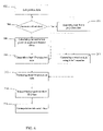
- FIG. 6 is a block diagram which illustrates an example of an embodiment of the logical flow of the image reconstruction method of variable pitch scanning
- FIG. 7A is a plot of an example of the error between the x-ray source trajectory and the reconstruction plane with the optimization of the tilt angle only.
- FIG. 7B is a plot of an example of the error between the x-ray source trajectory and the reconstruction plane with the optimization of the tilt angle and the distance offset.
- FIGS. 1 , 2 and 3 show perspective, end cross-sectional, and radial cross-sectional views, respectively, of a typical baggage scanning system 100 , which includes a conveyor system 110 for continuously conveying baggage or luggage 112 in a direction indicated by arrow 114 through a central aperture of a CT scanning system 120 .
- the conveyor system includes motor driven belts for supporting the baggage.
- Conveyer system 110 is illustrated as including a plurality of individual conveyor sections 122 ; however, other forms of conveyor systems may be used.
- the CT scanning system 120 includes an annular shaped rotating platform, or disk, 124 disposed within a gantry support 125 for rotation about a rotation axis 127 (shown in FIG. 3 ) that is preferably parallel to the direction of travel 114 of the baggage 112 .
- Disk 124 is driven about rotation axis 127 by any suitable drive mechanism, such as a belt 116 and motor drive system 118 , or other suitable drive mechanism, such as the one described in U.S. Pat. No. 5,473,657 issued Dec. 5, 1995 to Gilbert McKenna, entitled “X-ray Tomographic Scanning System,” which is assigned to the present assignee and, which is incorporated herein in its entirety by reference.
- Rotating platform 124 defines a central aperture 126 through which conveyor system 110 transports the baggage 112 .
- the system 120 includes an X-ray tube 128 and a detector array 130 which are disposed on diametrically opposite sides of the platform 124 .
- the detector array 130 is preferably a two-dimensional array, such as the array described in U.S. Pat. No. 6,091,795 entitled, “Area Detector Array for Computed Tomography Scanning System.” Other suitable arrays are known in the art.
- the system 120 further includes a data acquisition system (DAS) 134 for receiving and processing signals generated by detector array 130 , and an X-ray tube control system 136 for supplying power to, and otherwise controlling the operation of, X-ray tube 128 .
- DAS data acquisition system
- the system 120 is also preferably provided with a computerized system (not shown) for processing the output of the data acquisition system 134 and for generating the necessary signals for operating and controlling the system 120 .
- the computerized system can also include a monitor for displaying information including generated images.
- System 120 also includes shields 138 , which may be fabricated from lead, for example, for preventing radiation from propagating beyond gantry 125 .
- the X-ray tube 128 may generate a pyramidally-shaped beam, often referred to as a “cone beam,” 132 of X-rays that pass through a three dimensional imaging field, through which conveying system 110 transports baggage 112 .
- detector array 130 After passing through the baggage disposed in the imaging field, detector array 130 receives cone beam 132 and generates signals representative of the densities of exposed portions of baggage 112 .
- the beam therefore defines a scanning volume of space.
- Platform 124 rotates about its rotation axis 127 , thereby transporting X-ray source 128 and detector array 130 in circular trajectories about baggage 112 as the conveyor system 110 continuously transports baggage through central aperture 126 , so as to generate a plurality of projections at a corresponding plurality of projection angles.
- control system 136 supplies modulated high voltages with respect to alternating projection angles to the X-ray tube 128 .
- the detector array 130 then receives data corresponding to high-energy and low-energy X-ray spectra in alternating projection angles.
- FIG. 4A illustrates by way of example a three-section conveyor system 110 , which comprises three conveyor belts: an entrance conveyor belt 123 , a main conveyor belt 125 , and an exit conveyor belt 127 .
- Operators perform on-screen threat resolution for each scanned bag.
- the on-screen threat resolution includes resolving threats detected by automatic explosive and weapon detection algorithms and visually identifying prohibited items. For a complex bag, it may take more than the average time for operators to make a decision, and the conveyor system 110 has to be able to handle such a case.
- the entrance conveyor belt 123 stops taking any bags to the main conveyor belt.
- the exit conveyor belt 127 stops also after all the bags inside the main conveyor belt 125 are transported to the exit conveyor belt. Therefore, the portion of the exit conveyor belt from the position 129 to the end of the exit conveyor belt should be at least the same length as the main conveyor belt.
- the exit conveyor belt resumes by accelerating until it reaches its normal speed; with the entrance conveyor belt also resuming by accelerating until it reaches its normal speed.
- the baggage screening system thus returns to its normal operation mode.
- the main conveyor belt remains at a constant speed; therefore the CT scanner acquires projection data at a constant pitch.
- FIG. 4B illustrates an example of a two-section conveyor system.
- the main conveyor belt 125 has to perform the function of the entrance conveyor belt, that is, the main conveyor belt has to decelerate to a stop when operators take more than a pre-defined response time to make a decision.
- the exit conveyor belt can be shorter than the exit conveyor belt of a three-section conveyor system.
- the average response time limit position 129 can be at the end of the exit conveyor belt. After the main conveyor belt stops, typically the exit conveyor belt then decelerates to a stop.
- the main conveyor belt resumes and accelerates to its normal speed.
- the CT scanner acquires projection data at a variable pitch, which requires performing variable pitch image reconstruction.
- a typical deceleration (acceleration) of the belt is to stop (start) the belt from (to) its normal speed (e.g., a typical normal speed is 10 centimeters per second, although the speed that is considered normal can clearly vary) within one gantry rotation time (e.g., a typical time interval for one gantry rotation is 0.67 seconds, although this can clearly vary also).
- FIG. 5A shows an example of a belt speed profile of a belt decelerating from 10 cm/second to a complete stop in 0.67 seconds.
- 5 B shows an example of a belt speed profile of a belt accelerating from a complete stop to 10 cm/second in 0.67 seconds. Note that the gantry rotation speed usually does not change while the belt decelerates or accelerates; however, the disclosed method and system can directly apply to the scenarios where the gantry rotation speed also changes without any modification.
- One embodiment of the improved image reconstruction method provided in this disclosure can be implemented as an extension of the tilted or nutated 2D image reconstruction method for reconstructing helical cone beam data as described in “Advanced single-slice rebinning in cone-beam spiral CT,” Med. Phys., vol. 27, pp. 754-772, 2000 by M. Kachelriess, S. Schaller, and W.208, (hereinafter referred to as “ASSR Method”) and in U.S. Pat. No. 5,802,134.
- the advantage of using 2D image reconstruction over 3D cone beam reconstruction is the simplicity of incorporation of the variable pitch into the reconstruction, resulting in a faster and cheaper reconstruction system than using 3D reconstruction.
- the reconstruction plane is tilted to better fit the helix of the x-ray source trajectory.
- the tilt angle is a function of the pitch; therefore variable pitch image reconstruction can be accomplished by varying the tilt angle of the reconstruction plane.
- the second adaptation of the reconstruction plane is to shift the reconstruction along the Z-axis so that the error is minimized.
- FIG. 6 shows a block diagram of the logic flow of one embodiment of the image reconstruction method using variable pitch projection data.
- the conveyor belt position data is provided to the image reconstruction system.
- the following condition can be used for generating a new tilted slice: b ( t n+1 ) ⁇ b ( t n ) ⁇ d z (1)
- b(t n ) is the conveyor belt position at time t n of the n th tilted slice
- d z is the desired slice spacing for the tilted slices
- the condition of Eq. (1) is not met, the image reconstruction system will wait until the belt moves to the desired position while the CT scanner continues to acquire projection data as shown in Step 206 .
- a tilt angle, denoted by ⁇ ( ⁇ c ), for the reconstruction plane can be calculated as follows,
- ⁇ ⁇ ( ⁇ c ) - tan - 1 ⁇ ⁇ * ⁇ p ⁇ ( ⁇ c ) ⁇ w too ⁇ N rows 2 ⁇ ⁇ ⁇ ⁇ ⁇ R sc ⁇ sin ⁇ ⁇ ⁇ * ( 2 )
- w gao is the detector pitch along the Z direction at the isocenter
- N rows is the number of detector rows along the Z direction
- R sc is the distance from the source to the isocenter
- ⁇ c is the projection angle corresponding to the center view of the projection data for reconstructing the tilted slice
- p( ⁇ c ) is the helical scanning pitch at view angle ⁇ c
- ⁇ * is a constant calculated as follows,
- ⁇ * cos - 1 ⁇ 1 2 ⁇ ( 1 + cos ⁇ ⁇ ⁇ + ⁇ os 2 )
- ⁇ os is an over-scan angle and usually ranges from 10 to 20 degrees.
- the helical scanning pitch p( ⁇ c ) at view angle ⁇ c can be calculated as follows,
- N vprot is the number of sampling views (or projection angles) per rotation
- b(t v ) is the belt position at time t v corresponding to the center projection view angle ⁇ c
- b(t v ⁇ 1 ) is the belt position at time t v ⁇ 1 corresponding to the projection view which is one view before the center projection view angle ⁇ c .
- a 2D fan beam projection data set corresponding to a tilted angle described in Eq. (2) is generated in Step 210 from the cone-beam data acquired in Step 206 .
- the generation of the 2D fan beam projection data set typically comprises: A) computing the intersection line between the tilted reconstruction plane and the detector array; B) computing an index table and a weight table from the intersection line; and C) interpolating the cone-beam data using the computed index table and weight table to generate a 2D fan beam projection data set.
- intersection line between the tilted reconstruction plane and the detector array can be computed as follows,
- z ′ ⁇ ( v , s ) R sc ⁇ sin ⁇ ⁇ ⁇ ⁇ ( s ) ⁇ cos ⁇ ⁇ ⁇ r ⁇ ( v ) ⁇ tan ⁇ ⁇ ⁇ - p ⁇ ( a ⁇ ( v ) ) ⁇ N rows ⁇ w sio ⁇ ⁇ ⁇ ( v ) 2 ⁇ ⁇ ⁇ ⁇ cos ⁇ ⁇ ⁇ ⁇ ( s ) ( 2 ⁇ ⁇ A )
- z′(v,s) is the coordinate of the intersection line along the Z direction
- v is the view index
- s is the detector sample index along the fan direction
- ⁇ (s) is the fan angle with respect to the line connecting the x-ray source and the isocenter
- ⁇ r (v) is the projection angle with respect to the center view angle ⁇ c , of the tilted slice to be reconstructed
- p(a(v))
- index table denoted by I(v,s)
- W ⁇ ( v , s ) ⁇ 0 , r ′ ⁇ 0 r ′ - I ⁇ ( v , s ) , 0 ⁇ r ′ ⁇ N rows - 2 1 , r ′ > N rows - 2
- I(v,s) is the integer portion of the Z coordinate of the intersection line
- W(v,s) is the fraction portion of the Z coordinate of the intersection line.
- the error between the tilted reconstruction plane and the source helix is larger than at a constant pitch.
- Defrise et al. used John's equation to interpolate the projection data acquired at a constant pitch to correct the error between the source position and tilted reconstruction plane (M. Defrise, F. Noo, and H. Kudo, “Improved two-dimensional rebinning of helical cone-beam computerized tomography data using John's equation,” Inverse Problems , vol. 19, pp. S41-S54, 2003).
- John's equation can be used to correct the error between the source trajectory and the tilted reconstruction plane at variable pitch helical scanning to reduce the cone-beam image artifacts.
- correction data can be provided to compensate for the error between the source trajectory and the tilted reconstruction plane using John's equation at variable pitch helical scanning is generated at Step 211 .
- the generation of the correction data using John's equation comprises the following steps: A) converting the cylindrical detector coordinates to flat panel detector coordinates; B) computing the axial deviation between the tilted reconstruction plane and the source trajectory; C) computing the John's approximation coefficient term; D) computing the derivatives of the projection data; and E) generating the correction data. The details of one embodiment of these steps are described below.
- the flat panel detector coordinates denoted by ( ⁇ , ⁇ ), are calculated from the cylindrical coordinates (s,r) as follows,
- f ⁇ ⁇ ( ⁇ ⁇ ( v ) ) f ⁇ ( ⁇ ⁇ ( v ) ) - f ⁇ ( ⁇ ⁇ ( v - 1 ) ) ⁇ ⁇ ( v ) - ⁇ ⁇ ( v - 1 )
- the calculation of the second derivatives of the input projection data with respect to the projection angle and the detector column position is described below in detail.
- the input projection data denoted by P cone (v,s,r) in cylindrical detector coordinates, and is denoted by P( ⁇ , ⁇ , ⁇ ) in flat panel detector coordinates.
- the second derivatives needed for compensating the error include P ⁇ ( ⁇ , ⁇ , ⁇ ) and P ⁇ ( ⁇ , ⁇ , ⁇ ).
- the Taylor's series expansion is used to compute these derivatives.
- the projection data P( ⁇ , ⁇ , ⁇ 0 ) can be approximated using second order Taylor's expansion as follows,
- P ⁇ ( ⁇ , ⁇ , ⁇ 0 ) P ⁇ ( ⁇ , ⁇ , ⁇ ) + ( ⁇ 0 - ⁇ ) ⁇ P ⁇ ⁇ ( ⁇ , ⁇ , ⁇ ) + ( ⁇ 0 - ⁇ ) 2 2 ⁇ P ⁇ ⁇ ( ⁇ , ⁇ , ⁇ ) ( 3 ⁇ ⁇ A )
- P( ⁇ , ⁇ , ⁇ 1 ) and P( ⁇ , ⁇ , ⁇ 2 ) can also be approximated as follows,
- P ⁇ ( ⁇ , ⁇ , ⁇ 1 ) P ⁇ ( ⁇ , ⁇ , ⁇ ) + ( ⁇ 1 - ⁇ ) ⁇ P ⁇ ⁇ ( ⁇ , ⁇ , ⁇ ) + ( ⁇ 1 - ⁇ ) 2 2 ⁇ P ⁇ ⁇ ( ⁇ , ⁇ , ⁇ ) ( 3 ⁇ ⁇ B )
- P ⁇ ( ⁇ , ⁇ , ⁇ 2 ) P ⁇ ( ⁇ , ⁇ , ⁇ ) + ( ⁇ 2 - ) ⁇ P ⁇ ⁇ ( ⁇ , ⁇ , ⁇ ) + ( ⁇ 2 - ⁇ ) 2 2 ⁇ P ⁇ ⁇ ( ⁇ , ⁇ , ⁇ ) ( 3 ⁇ ⁇ C ) Therefore, given three projection values, P( ⁇ , ⁇ , ⁇ 0 ), P( ⁇ , ⁇ , ⁇ 1 ), P( ⁇ , ⁇ , ⁇ 2 ), the projection value
- ⁇ is
- the corrected fan-beam data then undergo a filtered back-projection operation to generate tilted slice images using, for example, the method described in “ Principles of Computerized Tomographic Imaging ,” Avinash C. Kak and Malcolm Slaney, IEEE Press, 1988.
- Step 216 tilted slices are interpolated along the Z axis on a pixel-by-pixel basis to form axial slices.
- a a [i,j,k] be the k th axial slice
- a t [i,j,l] be the l th tilted slice
- the axial slices are only formed at the same Z positions at the isocenter with the tilted slices; i.e. each axial slice intersects with one tilted slice.
- the calculation of the k th axial slice comprises: A) computing the Z distance between a set of tilted slices and the axial slice; B) computing weights for each pixel from two closest tilted slices, of which the axial pixel is in the middle; and C) interpolating the axial pixels using the pixels from the two closest tilted slices with the computed weights.
- the maximal tilt angle of the tilted slice is calculated according to the maximal pitch, thus the maximal number of tilted slices, denoted by N tilt , to generate one axial slice is calculated as follows,
- N tilt 1 + ⁇ 2 ⁇ ⁇ R fov ⁇ tan ⁇ ⁇ ⁇ max d z ⁇
- R fov is the radius of the reconstructed field of view
- d z is the slice spacing.
- (x 0 , y 0 ) is the image center with respect to the isocenter
- i,j are the pixel indices for each slice.
Abstract
Description
b(t n+1)−b(t n)≧d z (1)
where b(tn) is the conveyor belt position at time tn of the nth tilted slice, dz is the desired slice spacing for the tilted slices, and usually is the detector pitch (the distance between the centers of two consecutive detectors) along the Z direction (the conveyor belt moving direction) at the isocenter (the center of the rotation) of the scanner. If the condition of Eq. (1) is not met, the image reconstruction system will wait until the belt moves to the desired position while the CT scanner continues to acquire projection data as shown in
where wziso is the detector pitch along the Z direction at the isocenter, Nrows is the number of detector rows along the Z direction, Rsc is the distance from the source to the isocenter, αc is the projection angle corresponding to the center view of the projection data for reconstructing the tilted slice, p(αc) is the helical scanning pitch at view angle αc, and α* is a constant calculated as follows,
where Φos is an over-scan angle and usually ranges from 10 to 20 degrees. The helical scanning pitch p(αc) at view angle αc can be calculated as follows,
where Nvprot is the number of sampling views (or projection angles) per rotation, b(tv) is the belt position at time tv corresponding to the center projection view angle αc, b(tv−1) is the belt position at time tv−1 corresponding to the projection view which is one view before the center projection view angle αc.
A brute force search can be employed, by way of example, to find the optimal pair of φ(αc) and Z0(αc). The tilt angle calculated in Eq. (2) and the offset distance Z0(αc)=0 are used as initial values for the search. The search is within pre-defined limits of both variables. Adding the distance offset can further minimize the error between the source trajectory and the reconstruction plane, therefore resulting in further improved image quality.
where z′(v,s) is the coordinate of the intersection line along the Z direction, v is the view index, s is the detector sample index along the fan direction, γ(s) is the fan angle with respect to the line connecting the x-ray source and the isocenter, αr(v) is the projection angle with respect to the center view angle αc, of the tilted slice to be reconstructed, and p(a(v)) is the helical scanning pitch at view angle α(v)=αc+αr(v).
and └x┘ is the largest integer that is not greater than x.
The weight table, denoted by W(v,s), can be computed as follows,
Note that I(v,s) is the integer portion of the Z coordinate of the intersection line, and W(v,s) is the fraction portion of the Z coordinate of the intersection line. Therefore, the fan-beam projection data, denoted by Pfan(v,s), corresponding to the tilted reconstruction plane can be obtained from the cone-beam projection data, denoted by Pcone(v,s,r), as follows,
P fan(v,s)=P cone(v,s,I(v,s))(1−W(v,s))+P cone(v,s,I(v,s)+1)W(v,s)
where f(α) is the source position along the Z axis,
where fα(α) is the derivative of f(α), and is numerically calculated as follows,
Similarly, P(α,μ,υ1) and P(α,μ,υ2) can also be approximated as follows,
Therefore, given three projection values, P(α,μ,υ0), P(α,μ,υ1), P(α,μ,υ2), the projection value P(α,μ,υ), the first derivative Pυ(α,μ,υ)), and the second derivative Pυυ(α,μ,υ), for υ0<υ<υ1<υ2, can be obtained by solving the above three Eqs. (3A), (3B), and (3C).
P υ(α1,μ,υ)=P υ(α,μ,υ)+(α1−α)P αυ(α,μ,υ) (4A)
P υ(α2,μ,υ)=P υ(α,μ,υ)+(α2−α)P αυ(α,μ,υ) (4B)
Therefore, given two first derivatives of the projection values, Pυ(α,μ,υ) and Pυ(α2,μ,υ) the partial derivative Pαυ(α,μ,υ), for α1<α<α2 can be obtained by solving the above two Eqs. (4A) and (4B).
P J(α,μ)=C 1(α(v))(Γ1−Γ2)
where
where μ is at detector column position N, where there are total M columns of detectors, and υ is at the evaluated at the detector position according to Eq. (2A). The correction data PJ(α,μ) in flat panel detector coordinates can be directly mapped back to PJ(v,s) in cylindrical detector coordinates without additional calculation.
P fan J(v,s)=P fan(v,s)+P J(v,s)
In
where Rfov is the radius of the reconstructed field of view, and dz is the slice spacing.
z[i,j,l]=[x[i] cos α(l)+y[j] sin α(l)+Z 0(α(l))] tan Φ(l)+d z(l−l cen)
where dz is the slice spacing, α(l) is the central view index and Φ(l) is the tilt angle of the reconstructed slice and
where (x0, y0) is the image center with respect to the isocenter, and i,j are the pixel indices for each slice.
The linear interpolation weight for each pixel is then computed as follows,
A a [i,j,k]=A t [i,j,l max [i,j]]+w[i,j](A t [i,j,l min [i,j]+1]−A t [i,j,l max [i,j])
Note that the complexity of the above axial slice interpolation is reduced by storing the Z distance table for each rotation and for each discretized variable pitch within the range of the maximal pitch value.
Claims (11)
Priority Applications (1)
| Application Number | Priority Date | Filing Date | Title |
|---|---|---|---|
| US11/769,370 US7724866B2 (en) | 2007-06-27 | 2007-06-27 | Method of and system for variable pitch computed tomography scanning for baggage screening |
Applications Claiming Priority (1)
| Application Number | Priority Date | Filing Date | Title |
|---|---|---|---|
| US11/769,370 US7724866B2 (en) | 2007-06-27 | 2007-06-27 | Method of and system for variable pitch computed tomography scanning for baggage screening |
Publications (2)
| Publication Number | Publication Date |
|---|---|
| US20090003515A1 US20090003515A1 (en) | 2009-01-01 |
| US7724866B2 true US7724866B2 (en) | 2010-05-25 |
Family
ID=40160495
Family Applications (1)
| Application Number | Title | Priority Date | Filing Date |
|---|---|---|---|
| US11/769,370 Expired - Fee Related US7724866B2 (en) | 2007-06-27 | 2007-06-27 | Method of and system for variable pitch computed tomography scanning for baggage screening |
Country Status (1)
| Country | Link |
|---|---|
| US (1) | US7724866B2 (en) |
Cited By (9)
| Publication number | Priority date | Publication date | Assignee | Title |
|---|---|---|---|---|
| US20080285709A1 (en) * | 2007-05-04 | 2008-11-20 | Karl Schwarz | Imaging method for variable pitch spiral CT and a CT machine for carrying out the method |
| US20100215144A1 (en) * | 2009-02-26 | 2010-08-26 | Samit Kumar Basu | Method and system for performing a scan of an object |
| RU2595312C1 (en) * | 2014-05-14 | 2016-08-27 | Нуктех Кампани Лимитед | System of spiral ct and reconstruction methods |
| US10209205B2 (en) | 2014-04-29 | 2019-02-19 | Analogic Corporation | System and method for tire inspection |
| US20190204243A1 (en) * | 2017-12-28 | 2019-07-04 | Tsinghua University | Ct inspection system and ct imaging method |
| US20190204242A1 (en) * | 2017-12-28 | 2019-07-04 | Tsinghua University | Ct inspection system and ct imaging method |
| US10492756B2 (en) * | 2016-03-29 | 2019-12-03 | NeuroLogica Corporation, a subsidiary of Samsung Electronics Co., Ltd. | Correction for drive, tilt, and scanning-speed errors in imaging systems |
| US11039808B2 (en) | 2019-02-13 | 2021-06-22 | Analogic Corporation | Scanning systems configured to inspect conveyed objects and related systems and methods |
| US11717252B2 (en) | 2018-08-03 | 2023-08-08 | NeuroLogica Corporation, a subsidiary of Samsung Electronics Co., Ltd. | AI-based rendered volume auto-correction for fixed and mobile x-ray imaging modalities and other imaging modalities |
Families Citing this family (7)
| Publication number | Priority date | Publication date | Assignee | Title |
|---|---|---|---|---|
| US8086010B2 (en) * | 2006-06-30 | 2011-12-27 | Kabushiki Kaisha Toshiba | Medical image diagnosis apparatus and the control method thereof |
| US8027427B2 (en) * | 2009-08-31 | 2011-09-27 | Morpho Detection, Inc. | Systems and method for scanning a continuous stream of objects |
| JP6917378B2 (en) * | 2015-09-17 | 2021-08-11 | ファゾム・オプティクス・インコーポレイテッド | Multi-view display and related systems and methods |
| US10094950B2 (en) | 2016-07-11 | 2018-10-09 | Morpho Detection, Llc | System and method for detecting and reconstructing objects in a non-continuous stream of items in an imaging system |
| US11007772B2 (en) | 2017-08-09 | 2021-05-18 | Fathom Optics Inc. | Manufacturing light field prints |
| EP4111179A4 (en) * | 2020-02-27 | 2023-11-15 | Shenzhen Xpectvision Technology Co., Ltd. | Imaging system |
| CN112557425B (en) * | 2020-12-24 | 2023-01-10 | 北京航星机器制造有限公司 | CT detection device and tape stop control method |
Citations (50)
| Publication number | Priority date | Publication date | Assignee | Title |
|---|---|---|---|---|
| US5473657A (en) | 1994-02-08 | 1995-12-05 | Analogic Corporation | X-ray tomographic scanning system |
| US5802134A (en) | 1997-04-09 | 1998-09-01 | Analogic Corporation | Nutating slice CT image reconstruction apparatus and method |
| US5901198A (en) | 1997-10-10 | 1999-05-04 | Analogic Corporation | Computed tomography scanning target detection using target surface normals |
| US5932874A (en) | 1997-10-10 | 1999-08-03 | Analogic Corporation | Measurement and control system for controlling system functions as a function of rotational parameters of a rotating device |
| US5937028A (en) | 1997-10-10 | 1999-08-10 | Analogic Corporation | Rotary energy shield for computed tomography scanner |
| US5949842A (en) | 1997-10-10 | 1999-09-07 | Analogic Corporation | Air calibration scan for computed tomography scanner with obstructing objects |
| US5970113A (en) | 1997-10-10 | 1999-10-19 | Analogic Corporation | Computed tomography scanning apparatus and method with temperature compensation for dark current offsets |
| US5982844A (en) | 1997-10-10 | 1999-11-09 | Analogic Corporation | Computed tomography scanner drive system and bearing |
| US5982843A (en) | 1997-10-10 | 1999-11-09 | Analogic Corporation | Closed loop air conditioning system for a computed tomography scanner |
| US6026171A (en) | 1998-02-11 | 2000-02-15 | Analogic Corporation | Apparatus and method for detection of liquids in computed tomography data |
| US6026143A (en) | 1998-02-11 | 2000-02-15 | Analogic Corporation | Apparatus and method for detecting sheet objects in computed tomography data |
| US6035014A (en) | 1998-02-11 | 2000-03-07 | Analogic Corporation | Multiple-stage apparatus and method for detecting objects in computed tomography data |
| US6067366A (en) | 1998-02-11 | 2000-05-23 | Analogic Corporation | Apparatus and method for detecting objects in computed tomography data using erosion and dilation of objects |
| US6075871A (en) | 1998-02-11 | 2000-06-13 | Analogic Corporation | Apparatus and method for eroding objects in computed tomography data |
| US6076400A (en) | 1998-02-11 | 2000-06-20 | Analogic Corporation | Apparatus and method for classifying objects in computed tomography data using density dependent mass thresholds |
| US6078642A (en) | 1998-02-11 | 2000-06-20 | Analogice Corporation | Apparatus and method for density discrimination of objects in computed tomography data using multiple density ranges |
| US6091795A (en) | 1997-10-10 | 2000-07-18 | Analogic Corporation | Area detector array for computer tomography scanning system |
| US6108396A (en) | 1998-02-11 | 2000-08-22 | Analogic Corporation | Apparatus and method for correcting object density in computed tomography data |
| US6111974A (en) | 1998-02-11 | 2000-08-29 | Analogic Corporation | Apparatus and method for detecting sheet objects in computed tomography data |
| US6128365A (en) | 1998-02-11 | 2000-10-03 | Analogic Corporation | Apparatus and method for combining related objects in computed tomography data |
| US6195444B1 (en) | 1999-01-12 | 2001-02-27 | Analogic Corporation | Apparatus and method for detecting concealed objects in computed tomography data |
| US6256404B1 (en) | 1997-10-10 | 2001-07-03 | Analogic Corporation | Computed tomography scanning apparatus and method using adaptive reconstruction window |
| US6272230B1 (en) | 1998-02-11 | 2001-08-07 | Analogic Corporation | Apparatus and method for optimizing detection of objects in computed tomography data |
| US6292526B1 (en) * | 1999-10-27 | 2001-09-18 | General Electric Company | Methods and apparatus for preprocessing volumetric computed tomography data |
| US6317509B1 (en) | 1998-02-11 | 2001-11-13 | Analogic Corporation | Computed tomography apparatus and method for classifying objects |
| US6345113B1 (en) | 1999-01-12 | 2002-02-05 | Analogic Corporation | Apparatus and method for processing object data in computed tomography data using object projections |
| US6442228B1 (en) | 2000-04-20 | 2002-08-27 | Ge Medical Systems Global Technology Company, Llc | Data acquisition modifications for improved reconstruction with conventional CT |
| US20030072419A1 (en) * | 2001-07-09 | 2003-04-17 | Herbert Bruder | Computed tomography method and apparatus for acquiring images dependent on a time curve of a periodic motion of the subject |
| US6687326B1 (en) | 2001-04-11 | 2004-02-03 | Analogic Corporation | Method of and system for correcting scatter in a computed tomography scanner |
| US6721387B1 (en) | 2001-06-13 | 2004-04-13 | Analogic Corporation | Method of and system for reducing metal artifacts in images generated by x-ray scanning devices |
| US6748043B1 (en) | 2000-10-19 | 2004-06-08 | Analogic Corporation | Method and apparatus for stabilizing the measurement of CT numbers |
| US6813374B1 (en) | 2001-04-25 | 2004-11-02 | Analogic Corporation | Method and apparatus for automatic image quality assessment |
| US20050238232A1 (en) | 2004-04-26 | 2005-10-27 | Zhengrong Ying | Method and system for detecting threat objects using computed tomography images |
| US20050271293A1 (en) | 2004-06-04 | 2005-12-08 | Zhengrong Ying | Method of and system for destreaking the photoelectric image in multi-energy computed tomography |
| US20050276468A1 (en) | 2004-06-09 | 2005-12-15 | Zhengrong Ying | Method of and system for extracting 3D bag images from continuously reconstructed 2D image slices in computed tomography |
| US6977984B2 (en) | 2003-10-07 | 2005-12-20 | Ge Medical Systems Global Technology Company, Llc | Methods and apparatus for dynamical helical scanned image production |
| US20060002585A1 (en) | 2004-07-01 | 2006-01-05 | Larson Gregory L | Method of and system for sharp object detection using computed tomography images |
| US20060029180A1 (en) * | 2001-08-16 | 2006-02-09 | Alexander Katsevich | Exact filtered back projection (FBP) algorithm for spiral computer tomography with variable pitch |
| US20060039599A1 (en) | 2004-08-18 | 2006-02-23 | Anton Deykoon | Method of and system for detecting anomalies in projection images generated by computed tomography scanners |
| US7136450B2 (en) | 2004-05-26 | 2006-11-14 | Analogic Corporation | Method of and system for adaptive scatter correction in multi-energy computed tomography |
| US7136451B2 (en) | 2004-10-05 | 2006-11-14 | Analogic Corporation | Method of and system for stabilizing high voltage power supply voltages in multi-energy computed tomography |
| US20060274066A1 (en) | 2005-06-01 | 2006-12-07 | Zhengrong Ying | Method of and system for 3D display of multi-energy computed tomography images |
| US20070014471A1 (en) | 2005-07-18 | 2007-01-18 | Sergey Simanovsky | Method of and system for splitting compound objects in multi-energy computed tomography images |
| US20070014472A1 (en) | 2005-07-18 | 2007-01-18 | Zhengrong Ying | Method of and system for classifying objects using local distributions of multi-energy computed tomography images |
| US20070031036A1 (en) | 2005-08-04 | 2007-02-08 | Ram Naidu | Method of and system for classifying objects using histogram segment features of multi-energy computed tomography images |
| US7190757B2 (en) | 2004-05-21 | 2007-03-13 | Analogic Corporation | Method of and system for computing effective atomic number images in multi-energy computed tomography |
| US7197172B1 (en) | 2003-07-01 | 2007-03-27 | Analogic Corporation | Decomposition of multi-energy scan projections using multi-step fitting |
| US7224763B2 (en) | 2004-07-27 | 2007-05-29 | Analogic Corporation | Method of and system for X-ray spectral correction in multi-energy computed tomography |
| US7242749B2 (en) * | 2005-11-15 | 2007-07-10 | General Electric Company | Methods and systems for dynamic pitch helical scanning |
| US7492860B2 (en) * | 2006-04-04 | 2009-02-17 | Ge Security, Inc. | Apparatus and method for controlling start and stop operations of a computed tomography imaging system |
Family Cites Families (1)
| Publication number | Priority date | Publication date | Assignee | Title |
|---|---|---|---|---|
| FR2637600B1 (en) * | 1988-10-11 | 1992-03-06 | Pasteur Institut | PEPTIDES AND POLYPEPTIDES FROM THE RAT SUB-MAXILLARY GLAND, CORRESPONDING MONOCLONAL AND POLYCLONAL ANTIBODIES, HYBRIDOMAS AND APPLICATIONS THEREOF FOR DIAGNOSIS, DETECTION OR THERAPEUTIC PURPOSES |
-
2007
- 2007-06-27 US US11/769,370 patent/US7724866B2/en not_active Expired - Fee Related
Patent Citations (53)
| Publication number | Priority date | Publication date | Assignee | Title |
|---|---|---|---|---|
| US5473657A (en) | 1994-02-08 | 1995-12-05 | Analogic Corporation | X-ray tomographic scanning system |
| US5909477A (en) | 1997-04-09 | 1999-06-01 | Analogic Corporation | Computed tomography scanning target detection using non-parallel slices |
| US5802134A (en) | 1997-04-09 | 1998-09-01 | Analogic Corporation | Nutating slice CT image reconstruction apparatus and method |
| US5881122A (en) | 1997-04-09 | 1999-03-09 | Analogic Corporation | Computed tomography scanning apparatus and method for generating parallel projections using non-parallel slice data |
| US5887047A (en) | 1997-04-09 | 1999-03-23 | Analogic Corporation | Parallel processing architecture for computed tomography scanning system using non-parallel slices |
| US5932874A (en) | 1997-10-10 | 1999-08-03 | Analogic Corporation | Measurement and control system for controlling system functions as a function of rotational parameters of a rotating device |
| US6091795A (en) | 1997-10-10 | 2000-07-18 | Analogic Corporation | Area detector array for computer tomography scanning system |
| US5937028A (en) | 1997-10-10 | 1999-08-10 | Analogic Corporation | Rotary energy shield for computed tomography scanner |
| US5949842A (en) | 1997-10-10 | 1999-09-07 | Analogic Corporation | Air calibration scan for computed tomography scanner with obstructing objects |
| US5970113A (en) | 1997-10-10 | 1999-10-19 | Analogic Corporation | Computed tomography scanning apparatus and method with temperature compensation for dark current offsets |
| US5982844A (en) | 1997-10-10 | 1999-11-09 | Analogic Corporation | Computed tomography scanner drive system and bearing |
| US5982843A (en) | 1997-10-10 | 1999-11-09 | Analogic Corporation | Closed loop air conditioning system for a computed tomography scanner |
| US5901198A (en) | 1997-10-10 | 1999-05-04 | Analogic Corporation | Computed tomography scanning target detection using target surface normals |
| US6256404B1 (en) | 1997-10-10 | 2001-07-03 | Analogic Corporation | Computed tomography scanning apparatus and method using adaptive reconstruction window |
| US6317509B1 (en) | 1998-02-11 | 2001-11-13 | Analogic Corporation | Computed tomography apparatus and method for classifying objects |
| US6111974A (en) | 1998-02-11 | 2000-08-29 | Analogic Corporation | Apparatus and method for detecting sheet objects in computed tomography data |
| US6075871A (en) | 1998-02-11 | 2000-06-13 | Analogic Corporation | Apparatus and method for eroding objects in computed tomography data |
| US6076400A (en) | 1998-02-11 | 2000-06-20 | Analogic Corporation | Apparatus and method for classifying objects in computed tomography data using density dependent mass thresholds |
| US6078642A (en) | 1998-02-11 | 2000-06-20 | Analogice Corporation | Apparatus and method for density discrimination of objects in computed tomography data using multiple density ranges |
| US6035014A (en) | 1998-02-11 | 2000-03-07 | Analogic Corporation | Multiple-stage apparatus and method for detecting objects in computed tomography data |
| US6108396A (en) | 1998-02-11 | 2000-08-22 | Analogic Corporation | Apparatus and method for correcting object density in computed tomography data |
| US6067366A (en) | 1998-02-11 | 2000-05-23 | Analogic Corporation | Apparatus and method for detecting objects in computed tomography data using erosion and dilation of objects |
| US6128365A (en) | 1998-02-11 | 2000-10-03 | Analogic Corporation | Apparatus and method for combining related objects in computed tomography data |
| US6026171A (en) | 1998-02-11 | 2000-02-15 | Analogic Corporation | Apparatus and method for detection of liquids in computed tomography data |
| US6026143A (en) | 1998-02-11 | 2000-02-15 | Analogic Corporation | Apparatus and method for detecting sheet objects in computed tomography data |
| US6272230B1 (en) | 1998-02-11 | 2001-08-07 | Analogic Corporation | Apparatus and method for optimizing detection of objects in computed tomography data |
| US6195444B1 (en) | 1999-01-12 | 2001-02-27 | Analogic Corporation | Apparatus and method for detecting concealed objects in computed tomography data |
| US6345113B1 (en) | 1999-01-12 | 2002-02-05 | Analogic Corporation | Apparatus and method for processing object data in computed tomography data using object projections |
| US6292526B1 (en) * | 1999-10-27 | 2001-09-18 | General Electric Company | Methods and apparatus for preprocessing volumetric computed tomography data |
| US6442228B1 (en) | 2000-04-20 | 2002-08-27 | Ge Medical Systems Global Technology Company, Llc | Data acquisition modifications for improved reconstruction with conventional CT |
| US6748043B1 (en) | 2000-10-19 | 2004-06-08 | Analogic Corporation | Method and apparatus for stabilizing the measurement of CT numbers |
| US6687326B1 (en) | 2001-04-11 | 2004-02-03 | Analogic Corporation | Method of and system for correcting scatter in a computed tomography scanner |
| US6813374B1 (en) | 2001-04-25 | 2004-11-02 | Analogic Corporation | Method and apparatus for automatic image quality assessment |
| US6721387B1 (en) | 2001-06-13 | 2004-04-13 | Analogic Corporation | Method of and system for reducing metal artifacts in images generated by x-ray scanning devices |
| US20030072419A1 (en) * | 2001-07-09 | 2003-04-17 | Herbert Bruder | Computed tomography method and apparatus for acquiring images dependent on a time curve of a periodic motion of the subject |
| US20060029180A1 (en) * | 2001-08-16 | 2006-02-09 | Alexander Katsevich | Exact filtered back projection (FBP) algorithm for spiral computer tomography with variable pitch |
| US7197172B1 (en) | 2003-07-01 | 2007-03-27 | Analogic Corporation | Decomposition of multi-energy scan projections using multi-step fitting |
| US6977984B2 (en) | 2003-10-07 | 2005-12-20 | Ge Medical Systems Global Technology Company, Llc | Methods and apparatus for dynamical helical scanned image production |
| US20050238232A1 (en) | 2004-04-26 | 2005-10-27 | Zhengrong Ying | Method and system for detecting threat objects using computed tomography images |
| US7190757B2 (en) | 2004-05-21 | 2007-03-13 | Analogic Corporation | Method of and system for computing effective atomic number images in multi-energy computed tomography |
| US7136450B2 (en) | 2004-05-26 | 2006-11-14 | Analogic Corporation | Method of and system for adaptive scatter correction in multi-energy computed tomography |
| US20050271293A1 (en) | 2004-06-04 | 2005-12-08 | Zhengrong Ying | Method of and system for destreaking the photoelectric image in multi-energy computed tomography |
| US20050276468A1 (en) | 2004-06-09 | 2005-12-15 | Zhengrong Ying | Method of and system for extracting 3D bag images from continuously reconstructed 2D image slices in computed tomography |
| US20060002585A1 (en) | 2004-07-01 | 2006-01-05 | Larson Gregory L | Method of and system for sharp object detection using computed tomography images |
| US7224763B2 (en) | 2004-07-27 | 2007-05-29 | Analogic Corporation | Method of and system for X-ray spectral correction in multi-energy computed tomography |
| US20060039599A1 (en) | 2004-08-18 | 2006-02-23 | Anton Deykoon | Method of and system for detecting anomalies in projection images generated by computed tomography scanners |
| US7136451B2 (en) | 2004-10-05 | 2006-11-14 | Analogic Corporation | Method of and system for stabilizing high voltage power supply voltages in multi-energy computed tomography |
| US20060274066A1 (en) | 2005-06-01 | 2006-12-07 | Zhengrong Ying | Method of and system for 3D display of multi-energy computed tomography images |
| US20070014472A1 (en) | 2005-07-18 | 2007-01-18 | Zhengrong Ying | Method of and system for classifying objects using local distributions of multi-energy computed tomography images |
| US20070014471A1 (en) | 2005-07-18 | 2007-01-18 | Sergey Simanovsky | Method of and system for splitting compound objects in multi-energy computed tomography images |
| US20070031036A1 (en) | 2005-08-04 | 2007-02-08 | Ram Naidu | Method of and system for classifying objects using histogram segment features of multi-energy computed tomography images |
| US7242749B2 (en) * | 2005-11-15 | 2007-07-10 | General Electric Company | Methods and systems for dynamic pitch helical scanning |
| US7492860B2 (en) * | 2006-04-04 | 2009-02-17 | Ge Security, Inc. | Apparatus and method for controlling start and stop operations of a computed tomography imaging system |
Non-Patent Citations (11)
| Title |
|---|
| Bai et al., Study of an adaptive bolus chasing CT angiography, 2006, Journal of X-ray Science and Technology, vol. 14, pp. 27-38. * |
| Defrise, M., et al.; Improved two-dimensional rebinnin of helical cone-beam computerized tomography data using John's equation, Inverse Problems, vol. 19, pp. S41-S54, (2003). |
| Hsieh et al., Tilted cone-beam reconstruction with row-wise fan-to-parallel rebinning, 2006, Physics in Medicine and Biology, vol. 51, pp. 5259-5276. * |
| Kachelries, M., et al; Advanced single-slice rebinning in cone-beam spiral CT, Med. Phys., vol. 27, pp. 754-772, (2000). |
| Li et al., An Exact reconstruction algorithm in variable pitch helical cone-beam CT when PI-line exists, 2006, Journal of X-ray Science and Technology, vol. 14, pp. 109-118. * |
| Stierstorfer et al., Segmented multiple plane reconstruction: a novel approximate reconstruction scheme for multi-slice spiral CT, 2002, Physics in Medicine and Biology, vol. 47, pp. 2571-2581. * |
| Ye et al., Minimum detection windows, Pi-line existence and uniqueness for helical cone-beam scanning of variable pitch, 2004, Medical Physics, vol. 31, No. 3, pp. 566-572. * |
| Yu et al., A backprojection-filtration algorithm for nonstandard spiral cone-beam CT with an n-PI-window, 2005, Physics in Medicine and Biology, vol. 50, pp. 2099-2111. * |
| Zhou et al., Feldkamp-type reconstruction algorithms for spiral cone-beam CT with variable pitch, 2007, Journal of X-ray Science and Technology, vol. 15, pp. 177-196. * |
| Zou et al., Exact Image Reconstruction in a Helical Cone-beam Scan with a Variable Pitch, 2004, 2004 IEEE Nuclear Science Symposium Conference Record, vol. 7, pp. 4200-4203. * |
| Zou et al., PI-line-based image reconstruction in helical cone-beam computed tomography with a variable pitch, 2005, Medical Physics, vol. 32, No. 8, pp. 2639-2648. * |
Cited By (15)
| Publication number | Priority date | Publication date | Assignee | Title |
|---|---|---|---|---|
| US7978810B2 (en) * | 2007-05-04 | 2011-07-12 | Siemens Aktiengesellschaft | Imaging method for variable pitch spiral CT and a CT machine for carrying out the method |
| US20080285709A1 (en) * | 2007-05-04 | 2008-11-20 | Karl Schwarz | Imaging method for variable pitch spiral CT and a CT machine for carrying out the method |
| US20100215144A1 (en) * | 2009-02-26 | 2010-08-26 | Samit Kumar Basu | Method and system for performing a scan of an object |
| US7881426B2 (en) * | 2009-02-26 | 2011-02-01 | Morpho Detection, Inc. | Method and system for performing a scan of an object |
| US10209205B2 (en) | 2014-04-29 | 2019-02-19 | Analogic Corporation | System and method for tire inspection |
| RU2595312C1 (en) * | 2014-05-14 | 2016-08-27 | Нуктех Кампани Лимитед | System of spiral ct and reconstruction methods |
| US10492756B2 (en) * | 2016-03-29 | 2019-12-03 | NeuroLogica Corporation, a subsidiary of Samsung Electronics Co., Ltd. | Correction for drive, tilt, and scanning-speed errors in imaging systems |
| US20190204243A1 (en) * | 2017-12-28 | 2019-07-04 | Tsinghua University | Ct inspection system and ct imaging method |
| US20190204242A1 (en) * | 2017-12-28 | 2019-07-04 | Tsinghua University | Ct inspection system and ct imaging method |
| US10935691B2 (en) * | 2017-12-28 | 2021-03-02 | Tsinghua University | CT inspection system and CT imaging method for obtaining detection data at a frequency that is N times a beam-emitting frequency of a radioactive source device |
| US11327198B2 (en) * | 2017-12-28 | 2022-05-10 | Tsinghua University | CT inspection system and CT imaging method for a reciprocating swinging process of a radioactive source device and a detection device around an object at non-uniform speed to collect effective detection data |
| US11717252B2 (en) | 2018-08-03 | 2023-08-08 | NeuroLogica Corporation, a subsidiary of Samsung Electronics Co., Ltd. | AI-based rendered volume auto-correction for fixed and mobile x-ray imaging modalities and other imaging modalities |
| US11039808B2 (en) | 2019-02-13 | 2021-06-22 | Analogic Corporation | Scanning systems configured to inspect conveyed objects and related systems and methods |
| DE112020000793T5 (en) | 2019-02-13 | 2021-11-25 | Analogic Corporation | SCANNING SYSTEMS CONFIGURED TO VERIFY CARRIED OBJECTS, AND RELATED SYSTEMS AND PROCEDURES |
| US11523791B2 (en) | 2019-02-13 | 2022-12-13 | Analogic Corporation | Scanning systems configured to inspect conveyed objects and related systems and methods |
Also Published As
| Publication number | Publication date |
|---|---|
| US20090003515A1 (en) | 2009-01-01 |
Similar Documents
| Publication | Publication Date | Title |
|---|---|---|
| US7724866B2 (en) | Method of and system for variable pitch computed tomography scanning for baggage screening | |
| US5909477A (en) | Computed tomography scanning target detection using non-parallel slices | |
| US7190757B2 (en) | Method of and system for computing effective atomic number images in multi-energy computed tomography | |
| US7224763B2 (en) | Method of and system for X-ray spectral correction in multi-energy computed tomography | |
| US7136451B2 (en) | Method of and system for stabilizing high voltage power supply voltages in multi-energy computed tomography | |
| US7327853B2 (en) | Method of and system for extracting 3D bag images from continuously reconstructed 2D image slices in computed tomography | |
| US7324625B2 (en) | Contraband detection systems using a large-angle cone beam CT system | |
| US7970096B2 (en) | Method of and system for low cost implementation of dual energy CT imaging | |
| US7277577B2 (en) | Method and system for detecting threat objects using computed tomography images | |
| US5796802A (en) | Multiple angle pre-screening tomographic systems and methods | |
| US7136450B2 (en) | Method of and system for adaptive scatter correction in multi-energy computed tomography | |
| US7692650B2 (en) | Method of and system for 3D display of multi-energy computed tomography images | |
| US8472583B2 (en) | Radiation scanning of objects for contraband | |
| US8532259B2 (en) | Method and apparatus for computed imaging backscatter radiography | |
| US7801348B2 (en) | Method of and system for classifying objects using local distributions of multi-energy computed tomography images | |
| US7474786B2 (en) | Method of and system for classifying objects using histogram segment features of multi-energy computed tomography images | |
| US20060002585A1 (en) | Method of and system for sharp object detection using computed tomography images | |
| EP2721432B1 (en) | Security scanner | |
| JPH1082747A (en) | Square traverse ct detection method | |
| EP1021128A1 (en) | Computed tomography scanning target detection | |
| US8009883B2 (en) | Method of and system for automatic object display of volumetric computed tomography images for fast on-screen threat resolution | |
| US7415147B2 (en) | Method of and system for destreaking the photoelectric image in multi-energy computed tomography | |
| Smith et al. | CT technologies | |
| US7388983B2 (en) | Method of and system for detecting anomalies in projection images generated by computed tomography scanners |
Legal Events
| Date | Code | Title | Description |
|---|---|---|---|
| AS | Assignment |
Owner name: ANALOGIC CORPORATION, MASSACHUSETTS Free format text: ASSIGNMENT OF ASSIGNORS INTEREST;ASSIGNORS:NAIDU, RAM;KARBEYAZ, BASAK ULKER;YING, ZHENGRONG;AND OTHERS;REEL/FRAME:019768/0244;SIGNING DATES FROM 20070629 TO 20070706 Owner name: ANALOGIC CORPORATION,MASSACHUSETTS Free format text: ASSIGNMENT OF ASSIGNORS INTEREST;ASSIGNORS:NAIDU, RAM;KARBEYAZ, BASAK ULKER;YING, ZHENGRONG;AND OTHERS;SIGNING DATES FROM 20070629 TO 20070706;REEL/FRAME:019768/0244 |
|
| FPAY | Fee payment |
Year of fee payment: 4 |
|
| FEPP | Fee payment procedure |
Free format text: MAINTENANCE FEE REMINDER MAILED (ORIGINAL EVENT CODE: REM.) |
|
| AS | Assignment |
Owner name: MIDCAP FINANCIAL TRUST, MARYLAND Free format text: SECURITY INTEREST;ASSIGNORS:ANALOGIC CORPORATION;SOUND TECHNOLOGY, INC.;REEL/FRAME:046414/0277 Effective date: 20180622 |
|
| LAPS | Lapse for failure to pay maintenance fees |
Free format text: PATENT EXPIRED FOR FAILURE TO PAY MAINTENANCE FEES (ORIGINAL EVENT CODE: EXP.) |
|
| STCH | Information on status: patent discontinuation |
Free format text: PATENT EXPIRED DUE TO NONPAYMENT OF MAINTENANCE FEES UNDER 37 CFR 1.362 |
|
| FP | Lapsed due to failure to pay maintenance fee |
Effective date: 20180525 |
|
| FEPP | Fee payment procedure |
Free format text: PETITION RELATED TO MAINTENANCE FEES FILED (ORIGINAL EVENT CODE: PMFP); ENTITY STATUS OF PATENT OWNER: LARGE ENTITY Free format text: SURCHARGE, PETITION TO ACCEPT PYMT AFTER EXP, UNINTENTIONAL (ORIGINAL EVENT CODE: M1558); ENTITY STATUS OF PATENT OWNER: LARGE ENTITY |
|
| FEPP | Fee payment procedure |
Free format text: PETITION RELATED TO MAINTENANCE FEES DISMISSED (ORIGINAL EVENT CODE: PMFS); ENTITY STATUS OF PATENT OWNER: LARGE ENTITY |
|
| AS | Assignment |
Owner name: ANALOGIC CORPORATION, MASSACHUSETTS Free format text: RELEASE BY SECURED PARTY;ASSIGNOR:MIDCAP FINANCIAL TRUST;REEL/FRAME:064917/0544 Effective date: 20230914 |